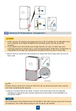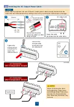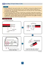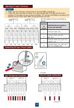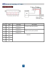
COM Port Pin Definitions
No.
Label
Definition Description
1
OUT+
Battery enabling /-
2
OUT-
12V_OUT–
3
A1
RS485A1
Southbound RS485 port for connecting to the battery RS485 port
4
B1
RS485B1
5
A2
RS485A2
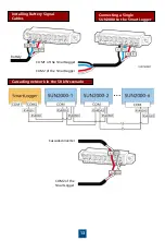
Connects to the COM1 signal port on the SmartLogger
6
B2
RS485B2
7
A3
RS485A3
Connects to the COM2 signal port on the SmartLogger or cascades
inverters
8
B3
RS485B3
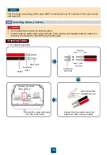
Installing Signal Cables
3.7
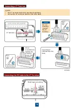
When laying out a signal cable, separate it from power cables and keep it away from strong
interference sources to prevent communication interruption.
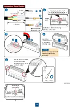
If multiple signal cables need to be connected, ensure that the outer diameters of the signal
cables are the same.
11
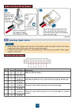
Battery Terminal Wiring Diagram
Insert the battery terminal that has
been connected into the base and
secure the yellow part of the battery
terminal to the base.
Connect the positive
and negative cables
according to the labels.
Pull the
battery cables
back to check
that they are
securely
connected.


