14
7
Powering On the System
1. Turn on the AC switch between the SUN2000 and the power grid.
2. Ensure that the DC switches at the chassis bottom are ON.
3. (Optional) Measure the temperatures at the joints between DC terminals and connectors using a
point-test thermometer.
4. Observe the indicators to check the SUN2000 operating status.
Before turning on the AC switch between the SUN2000 and the power grid, use a multimeter to
check that the AC voltage is within the operating voltage range of the SUN2000.
To ensure that the DC terminals are in good contact, check the temperatures at the joints between
DC terminals and connectors after the SUN2000 has been running for a period of time. Ensure that
the temperature rise does not exceed 40
°
C (104
°
F).
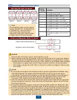
Indicator
Status
Description
PV connection
indicator
Steady green
At least one PV string is properly connected,
and the DC input voltage of the corresponding
MPPT circuit is higher than or equal to 200 V.
Off
The SUN2000 disconnects from all PV strings,
or the DC input voltage of each MPPT circuit is
less than 200 V.
Grid-tied
indicator
Steady green
The SUN2000 has connected to the power
grid.
Off
The SUN2000 does not connect to the
power grid.
Communications
indicator
Blinking green (on for 0.5s and
then off for 0.5s)
The SUN2000 receives data over RS485/PLC
communication.
Off
The SUN2000 has not received data over
RS485/PLC communication for 10 seconds.
Alarm/
Maintenance
indicator
Alarm status
Blinking red at long
intervals (on for 1s
and then off for 4s)
A warning alarm is generated.
Blinking red at
short intervals (on
for 0.5s and then
off for 0.5s)
A minor alarm is generated.
Steady red
A major alarm is generated.
Local
maintenance
status
Blinking green at
long intervals (on
for 1s and then off
for 1s)
Local maintenance is in progress.
Blinking green at
short intervals (on
for 0.125s and then
off for 0.125s)
Local maintenance fails.
Steady green
Local maintenance succeeds.
NOTICE
NOTE


