11
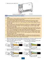
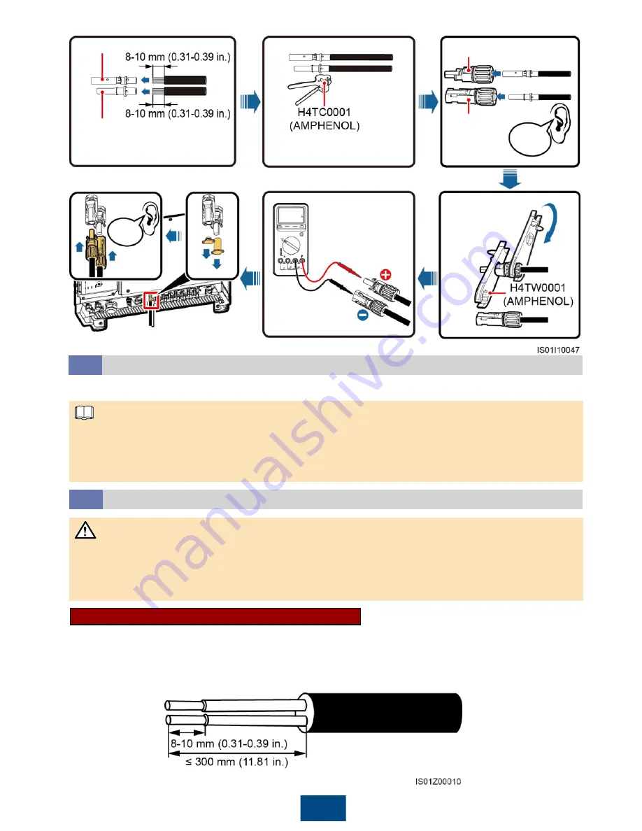
Positive connector
Negative
connector
Positive metal terminal
Negative metal terminal
Recommended: 12 AWG PV
cable (PV1-F)
Ensure that the cable cannot
be removed after crimped.
Click
Ensure that
the locking nut
is secured.
Ensure that the
cables are correctly
connected and that
the voltage does not
exceed 1000 V DC.
Click
1. If PLC is used, you do not have to connect any communications cable to the SUN2000, but
have to connect the PLC CCO module or SmartLogger2000 to the AC power cable. For detailed
operations, see the
PLC CCO01A User Manual
or
SmartLogger2000 User Manual
.
2. If RS485 is used, do not connect the PLC CCO module to the AC power cable.
Installing the RS485 Communications Cable
5.8
1. When routing communications cables, separate communications cables from power cables to
prevent communication from being affected by signal interference.
2. An RS485 cable can connect to either a terminal block or an RJ45 network port. It is
recommended that the RS485 cable connect to a terminal block.
Selecting a Communication Mode
5.7
The SUN2000 supports either PLC or RS485 communication mode.
Terminal Block Connection (Recommended)
Recommended: outdoor communications cable with a conductor cross-sectional area of 18 AWG
and an outer diameter range of 14 mm to 18 mm (0.55 in. to 0.71 in.)
1. Remove an appropriate length of the jacket and core wire insulation layer from the
communications cable using a wire stripper.
NOTICE
NOTE


