background image

Installation Manual 
Quidway S3526 Ethernet Switch 

Chapter 5  Booting and Configuration


5-5 

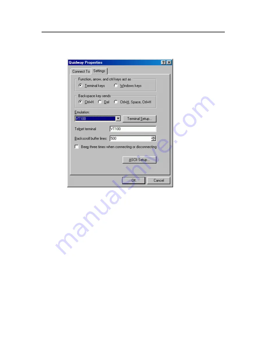
Select [Properties] in the Hyper Terminal dialog box to enter the property window. Click 

[Settings] in the property setting window as the following figure and select the 

emulation terminal to VT100. Click <OK> when the selection is done. 


Figure 5-6


Setting the terminal emulation in property setting window 

5.4  Booting S3526 Switch 

5.4.1  Check before Powering on the Switch 

Before powering on S3526 switch, check that: 


The power cords and ground wires are correctly connected. 


The voltage is consistent with that required by the switch. 


The console cable is correctly connected; the PC or the terminal for configuration 

has been started; and the setting is completed. 

Содержание Quidway S3526

Страница 1: ...HUAWEI Quidway S3526 Ethernet Switch Installation Manual VRP3 10 ...

Страница 2: ...ase the products from the sales agent of Huawei Technologies Co Ltd please contact our sales agent If you purchase the products from Huawei Technologies Co Ltd directly Please feel free to contact our local office customer care center or company headquarters Huawei Technologies Co Ltd Address Administration Building Huawei Technologies Co Ltd Bantian Longgang District Shenzhen P R China Postal Cod...

Страница 3: ... Tellwin Inmedia VRP DOPRA iTELLIN HUAWEI OptiX C C08iNET NETENGINE OptiX iSite U SYS iMUSE OpenEye Lansway SmartAX infoX TopEng are trademarks of Huawei Technologies Co Ltd All other trademarks mentioned in this manual are the property of their respective holders Notice The information in this manual is subject to change without notice Every effort has been made in the preparation of this manual ...

Страница 4: ... x VRRP and system management Organization Quidway S3526 Ethernet Switch Installation Manual mainly introduces the hardware features installation configuration and maintenance of S3526 To avoid any possible device damage and personal injury before the installation and during the installation please read the manual carefully The manual consists of the following chapters z Chapter 1 Overview The cha...

Страница 5: ...e Modules The chapter introduces the interface modules supported by S3526 z Appendix A Knowledge of Optical Fiber The appendix introduces the general information of optical fiber including the fiber classification and the optical fiber connectors Appendix B RJ 45 Connector The appendix introduces the general information of RJ 45 connector Appendix C Lightning Protection of Switches The appendix in...

Страница 6: ... maximum of all can be selected x y Optional alternative items are grouped in square brackets and separated by vertical bars Many or none can be selected III GUI conventions Convention Description Button names are inside angle brackets For example click the OK button Window names menu items data table and field names are inside square brackets For example pop up the New User window Multi level men...

Страница 7: ...lso used in the manual to highlight the points worthy of special attention during the operation They are defined as follows Caution Warning Danger Means reader be extremely careful during the operation Note Comment Tip Knowhow Thought Means a complementary description Environmental Protection This product has been designed to comply with the requirements on environmental protection For the proper ...

Страница 8: ... 2 2 3 Console Port 2 2 2 3 Rear Panel of S3526 Switch 2 3 2 3 1 Rear Panel of AC Chassis 2 3 2 3 2 Rear Panel of DC Chassis 2 3 2 3 3 Optional Interface Module 2 4 2 4 System Features of S3526 Switch 2 5 Chapter 3 Installation Preparation 3 1 3 1 Precautions 3 1 3 2 Requirements on Environment 3 1 3 2 1 Temperature Humidity Requirements 3 1 3 2 2 Cleanness Requirement 3 2 3 2 3 Anti interference ...

Страница 9: ...oftware Loading 6 1 6 2 1 Boot Menu 6 2 6 2 2 Loading Software from Console Port Using XModem 6 3 6 2 3 Loading Software from Ethernet Port Using TFTP 6 8 6 2 4 Loading Software from Ethernet Port Using FTP 6 9 6 3 Remote Software Loading 6 11 6 3 1 Remote Loading Using FTP 6 11 6 3 2 Remote Loading Using TFTP 6 12 6 4 Dealing with Load Failure 6 12 6 5 Dealing with Missing of Password 6 13 Chapte...

Страница 10: ...7 1 Introduction 8 8 8 7 2 Appearance 8 9 8 7 3 Module Panel and the Indicators 8 9 8 7 4 Connection of Module Interface Cable 8 10 Appendix A Knowledge of Optical Fiber A 1 A 1 Multi mode Optical Fiber and Single Mode Optical Fiber A 1 A 2 Optical Fiber Connector A 1 Appendix B RJ 45 Connector B 1 Appendix C Lightning Protection of Switches C 1 C 1 Installation of Lightning Arrester for Power Soc...

Страница 11: ... used in the networking of enterprise network IP MAN Metropolitan Area Network and residential quarter The services supported by Quidway S3526 Ethernet Switch include Internet broadband access Networking of enterprise network and campus network Multicast service and multicast routing functions Supports multicast Audio Video services and VOD services 1 2 Typical Application of S3526 Switch The netw...

Страница 12: ...3026 S3026 S2403 S3026 S3526 Core layer devices Convergence layer devices Access layer devices in a residential quarter or a building Desk top access layer devices Local service center Figure 1 1 Networking of Ethernet access 1 2 2 Networking of VDSL Access in Broadband Residential Quarter In the networking application of a broadband residential quarter S3526 Ethernet Switch can be downstream conn...

Страница 13: ...orking of Medium and Small Sized Enterprises Branches of Large Enterprises In medium and small sized enterprises and the branches of large enterprises S3526 switch can be used as backbone switch and connected to the headquarters or the network of other branches via the routers When the scale of the enterprise expands S3526 switches can be used in the cascade mode to scale up the backbone network ...

Страница 14: ...ing of Large Enterprise and Campus In large scale enterprise network and the campus network S3526 are located in the convergence layer attached with several layer 2 Ethernet switches such as Quidway S3026 Ethernet Switch In the upstream direction S3526 switches are connected to the core layer 3 switches via the GE expansion module slots Thereby it offers a complete enterprise networking solution w...

Страница 15: ...rver server server server PC PC PC Enterprise backbone L2 L3 100M 1000M GE 1000M L2 L3 100M 1000M Server cluster L3 S3526 S3526 Department server S2403 S3026 desktop L2 10M 100M L2 L3 100M 1000M FE 100M S3526 Figure 1 4 Networking of large enterprise network and campus network ...

Страница 16: ...C chassis have the same front panel 2 2 1 Front Panel As illustrated in the following figure there are from left to right the power indicator 24 fixed 10Base T 100Base TX Ethernet interfaces and a Console port on the front panel of S3526 switch Power indicator Console port CONSOLE Figure 2 2 Front panel of S3526 Ethernet Switch The meaning of the indicators on the front panel of S3526 Ethernet Swi...

Страница 17: ...X 2 2 2 Ethernet Interface The Ethernet interface on the front panel uses the connector with indicators The connector type is of standard RJ 45 The attributes of the Ethernet interface are listed in the following table Table 2 2 Attribute of 10Base T 100Base TX interface Attribute S3526 Type of connector RJ 45 Number of interfaces 24 Functions 100Mbps full duplex 10M full duplex MDI MDI X auto sen...

Страница 18: ...t can be selected Please refer to section 6 2 2 3 Rear Panel of S3526 Switch 2 3 1 Rear Panel of AC Chassis On the rear panel of S3526 s AC chassis there are AC power input socket two optional interface module slots and grounding screw from left to right as illustrated in the following figure AC power input Grounding screw 100 240V AC LINK ACTIVE LINK ACTIVE Figure 2 3 Rear panel of S3526 Ethernet...

Страница 19: ... 4 Rear panel of S3526 Ethernet Switch DC chassis 2 3 3 Optional Interface Module The types of the optional interface modules supported by S3526 Ethernet Switch are listed in the following 1000Base SX module 1000Base LX module 1000Base T module 1000Base ZX module 70km 1000Base LX GL module 40km Stack module For detailed features of each module please refer to Chapter 8 ...

Страница 20: ...lude 1000Base T module 1000Base LX module 1000Base SX module 1000Base ZX module 70km 1000Base LX GL module 40km stack module Switching mode Store and forward Switching capacity 12 8Gbps Packet processing capability 6 55Mpps MAC address aging time 5 minutes default VLAN Supports 4k port based VLANs compliant with IEEE 802 1Q standard MAC address list Supports up to 16K MAC addresses and 16K IP addr...

Страница 21: ...tion to protect the safe of the operator and the switch 3 2 Requirements on Environment S3526 Ethernet Switch should be used indoors The following requirements must be met irrespective of whether you install the switch in 19 inch standard cabinet or install it directly on the workbench Make sure that enough room is left for the air intake hole and the ventilation hole of the switch so that the hea...

Страница 22: ... Falling on the equipment it may cause electrostatic adsorption and hence result in poor contact of the metal connectors or connection points This is more likely to happen when the relative indoor humidity is low which will not only shorten the router s service life but also incur communication failures The requirements on dust content and particle diameter in the equipment room are shown in the f...

Страница 23: ...h far away from radio launcher radar launcher and high frequency devices working in high currents Adopt the measure of electromagnetic shielding if necessary For example you can adopt shielded interface cable Interface cable must be run indoors and outdoor cabling is not permitted in case that overvoltage and overcurrent damage the device Caution If the cable has to be run outdoors please select p...

Страница 24: ...tch Chapter 3 Installation 3 4 3 3 Installation Tools Phillips screwdriver Flat blade screwdriver ESD preventive wrist strap Note The installation tools are not shipped with S3526 switch You must ensure the availability of required tools beforehand ...

Страница 25: ...e Installation 4 1 1 Installing the Switch in 19 inch Standard Cabinet The installation procedures are described in the following sections Step 1 Check grounding and stability of the cabinet Fix the angle iron at both sides of the front panel of the switch with screws Step 2 Place the switch on a shelf in the cabinet Depending on the actual situation slide the switch along the guides of the cabine...

Страница 26: ...h You need to pay attention to the following during such operation Make sure that the workbench is secure and well grounded Leave about 10 centimeters of space around the switch for heat dissipation Do not place heavy objects on top of the switch 4 2 Connection of Power Cord and Ground Wire S3526 Ethernet Switch supports two types of power modules i e AC power module and DC power module Users can ...

Страница 27: ...ltage 100 240V a c 50 60Hz Maximum voltage 90 264V a c 50 60Hz See the AC power source in the following figure AC input 100 240V AC Figure 4 2 Partial look of the switch power socket AC power Note S3526 Ethernet Switch with AC power input has no power switch on its panel II Recommended AC power socket A monophase 3 wire power socket with a neutral point connector or a multi functional power socket...

Страница 28: ... that is shipped with the switch to the power socket on the rear panel of the switch chassis and connect the other end to AC power socket Step 3 Check whether the power indicator on the front panel of the switch is on If it is on it indicates that the power cords are correctly connected 4 2 2 DC Power Supply and Power Cords I DC power Rated voltage 60 48V d c Maximum voltage 72 36V d c DC power in...

Страница 29: ...power cord is correctly connected 4 2 3 Ground Wire Note The correct connection of the switch ground wire is the primary guarantee for the lightning protection and anti interference requirement for a switch so you should connect the ground wire carefully The power input end of S3526 Ethernet Switch is connected with a noise filter unit whose central ground is directly connected with the chassis fo...

Страница 30: ...d RJ 45 connector which is to be plugged into the console port of the switch The other end is furnished with a DB 9 pin connector and a DB 25 pin connector You can select either of them based on your actual requirement to fit in with the 25 pin or 9 pin interface on the configuration terminal The Console cable is shown in the following figure Enlarged A side Pos 25 A DB 25 Female 8P8C Plug Enlarge...

Страница 31: ...serial port of the PC or the terminal then plug the RJ 45 connector of the console cable to the console port of the switch When disconnect the PC and switch please first unplug the RJ 45 connector of the console cable to the console port of the switch then unplug the DB 9 or DB 25 female plug of the console cable to the serial port of the PC or the terminal 4 4 AUX Cable Connection AUX cable is ne...

Страница 32: ...5 Signal Direction DB 25 DB 9 1 RTS 4 7 2 DTR 20 4 3 TXD 2 3 4 CD 8 1 5 GND 7 5 6 RXD 3 2 7 DSR 6 6 8 CTS 5 8 4 4 2 Connecting AUX Cable Step 1 Plug the RJ 45 end of the AUX cable into the switch Console Step 2 Connect the DB 25 or DB 9 end of the AUX cable into the Modem serial port 4 5 Installation of the Optional Interface Modules Refer to Chapter 8 for detailed description 4 6 Post installatio...

Страница 33: ...on the switch The ground wire is connected The Console cable and power input cable are connected properly Check if all the interface cabling is performed indoors and there is no outdoor cabling In the case of outdoor cabling check if the socket strip with lightning protection and network port lightning arrester have been connected ...

Страница 34: ...tions parameters Console cable Switch PC Figure 5 1 Setting up the local terminal configuration environment 5 2 Connecting the Console Cable Step 1 Plug the DB 9 25 connector of the console cable to the serial interface of the PC or terminal where the switch is to be configured Step 2 Connect the RJ 45 connector of the console cable to the console of the switch 5 3 Setting Parameters of the Termin...

Страница 35: ...tart Program Accessories Communications Hyper Terminal to enter the Hyper Terminal window in which click icon to establish a new connection and the system will pop up the connection description interface Figure 5 2 Connection description interface of HyperTerminal 2 Key in the name of the new connection in the connection description interface and click OK the system will pop up the following inter...

Страница 36: ...iguration 5 3 Figure 5 3 Setting the serial port to be used in HyperTerminal connection 3 Click OK after the serial port is selected and the system will pop up the following interface Set the baud rate to 9600 data bit to 8 no parity check stop bit to 1 and flow control to none ...

Страница 37: ... Ethernet Switch Chapter 5 Booting and Configuration 5 4 Figure 5 4 Setting serial interface parameters 4 Click OK when the serial interface parameters are set and the system will enter the following interface Figure 5 5 HyperTerminal ...

Страница 38: ...nal to VT100 Click OK when the selection is done Figure 5 6 Setting the terminal emulation in property setting window 5 4 Booting S3526 Switch 5 4 1 Check before Powering on the Switch Before powering on S3526 switch check that The power cords and ground wires are correctly connected The voltage is consistent with that required by the switch The console cable is correctly connected the PC or the t...

Страница 39: ...eck port leds Led selftest finished 3 Flash fast selftest OK 4 Switch chip selftest OK 5 CPLD selftest OK 6 Port g2 1 has no module 7 Port g1 1 has no module 8 PHY selftest OK 9 SSRAM fast selftest OK 10 Press Ctrl B to enter Boot Menu 5 11 Line 1 to 10 indicates system selftest information line 7 and 8 may be changed based on different modules For the line 11 5 seconds are kept for the instructio...

Страница 40: ...auto booting of the system the switch will start the decompression Auto booting Decompress Image OK Starting application now User interface Aux0 0 is available Press ENTER to get started Press Enter and the terminal display will give the following output Quidway Now you can configure the switch Note Quidway series switch provides a variety of command modes For the specific description on the confi...

Страница 41: ...se note that the BootROM version should be compatible with the host software version when BootROM and host software are being loaded 6 2 Local Software Loading If your terminal is directly connected to the switch you can load BootROM and host software at the local Before proceeding to load the software make sure that your terminal is correctly connected to the switch Note The steps that you should...

Страница 42: ...st selftest OK Please check port leds Led selftest finished Flash fast selftest OK Switch chip selftest OK CPLD selftest OK Port g2 1 has no module Port g1 1 has no module PHY selftest OK SSRAM fast selftest OK Press Ctrl B to enter Boot Menu 5 Press Ctrl B The system displays Password Note To access the Boot Menu you should press Ctrl B within five seconds after the information Press Ctrl B to en...

Страница 43: ...of retransmission attempts is ten XModem transmission is completed by receiving program and sending program Receiving program initiates packet checking method negotiation by sending the negotiation character If the negotiation passes sending program starts packet transmission Upon the receipt of a complete packet the receiving program checks it using the agreed upon check method If the check succe...

Страница 44: ...er The system displays the following information Are you sure to update your bootrom Y N Step 4 The system begins to download if you press Y it returns to download menu if you press N If you press Y and Enter the system displays the following information Download baudrate is 115200 bps Please change the terminal s baudrate to 115200 bps and select XMODEM protocol Press enter key when ready Note Yo...

Страница 45: ...Installation Manual Quidway S3526 Ethernet Switch Chapter 6 BootROM and Host Software Loading 6 5 Figure 6 1 Properties dialog box Figure 6 2 Console Port Configuration dialog box ...

Страница 46: ...nect the terminal emulation program to validate the new configuration Step 7 Press Enter to start program loading The system displays the following information Now please start transfer file with XMODEM protocol If you want to exit Press Ctrl X Loading CCCCCCCCCC Step 8 Select Transfer Send File in the HyperTerminal s window and in the popup dialog box similar to the following figure click Browse ...

Страница 47: ...if you have chosen 9600 bps In this case the system does not display the above prompt message but BootROM is updating now done instead Step 10 Reset HyperTerminal s baud rate to 9600bps with reference to Steps 5 and 6 described above Then press any key as prompted The system will display the following information when it completes the loading Bootrom is updating now done III Loading host software ...

Страница 48: ...u should know PC s IP address Besides connect the switch to an external PC via Console port This PC can be the same one storing the files to be downloaded Step 2 Run the TFTP Server program on the PC connected to the Ethernet port and specify the path for program loading Caution TFTP Server program is not provided with the Quidway Series Switches Step 3 Run terminal emulation program on the PC tha...

Страница 49: ...gram downloading and upon its completion automatically starts BootROM loading The system displays the following information upon the completion of the entire process Initializing net done Loading done Bootrom is updating now done III Loading host software Follow these steps to download the host software of the switch Step 1 Select 1 in Boot Menu The system displays the following information 1 Set ...

Страница 50: ...m download protocol parameter 1 Set TFTP protocol parameter 2 Set FTP protocol parameter 3 Set XMODEM protocol parameter 0 Return to boot menu Step 4 In the download protocol menu press 2 to select FTP protocol to download BootROM and host software Press Enter The system displays the following information Load File name Switch IP address That address is in the same network segment as the server IP...

Страница 51: ... switch by a network you can load BootROM and host software at the remote 6 3 1 Remote Loading Using FTP Run FTP Server on a local PC provided you have configured username and password and have set the correct file directory Suppose IP address of the PC is 10 10 110 1 Log onto the switch via Telnet to send host program to the switch using FTP Provided that the host program is SWITCH app and the Bo...

Страница 52: ...uring loading process 6 3 2 Remote Loading Using TFTP Using TFTP is similar to using FTP in remote loading The only difference is that it is TFTP that you use when loading software to the switch In this case the switch can only be used as a TFTP client to download the software to its Flash memory from the TFTP server The remaining steps after downloading are the same as those of remote loading usi...

Страница 53: ...er and switch IP addresses Correct name of the software to be loaded Correct username and password If loading fails when there are neither physical connection problems nor input errors please contact the local agents of Huawei Technologies Co Ltd for help 6 5 Dealing with Missing of Password Please contact the local agent of Huawei Technologies Co Ltd if the BootROM password or user password of th...

Страница 54: ...at the configuration terminal or the displayed characters will be totally illegible I Troubleshooting when there is no terminal display If there is no output information after the configuration is powered on please check that whether the power supply is normal whether the console cables are connected correctly If no problems are found after the above mentioned items have been checked the cause may...

Страница 55: ...26 Ethernet Switch provides the following types of optional interface modules 1000Base SX module 1000Base LX module 1000Base T module 1000Base ZX module 1000Base LX module stack module 8 2 Installation of the Optional Modules For the description of the function module Installation please refer to Chapter 3 I Installation Tools Flat blade screw driver ESD preventive wrist strap II Installation Warn...

Страница 56: ...terface card on the switch with the captive screw on the card of the function module III Removal Step 1 Wear ESD preventive wrist strap to disconnect the power of the switch Step 2 Place the switch on a surface with its rear panel forward Step 3 Use a flat blade screwdriver to unscrew the captive screws on the both sides of the optional interface module Step 4 Unseat the interface card in the dire...

Страница 57: ...n distance when 62 5 125µm multi mode optical fiber is selected 550m transmission distance when 50 125µm multi mode optical fiber is selected 220m transmission distance when 62 5 125µm multi mode optical fiber is selected 500m transmission distance when 50 125µm multi mode optical fiber is selected Compliant standard IEEE 802 3 z Central wavelength 1300nm 850nm Transmitting optical power 9 5dBm Re...

Страница 58: ...anel indicators is given in the following table Table 8 3 Meaning of indicators on 1000Base SX module panel Indicator State LINK Off means the line is not connected On means the line is connected ACTIVE Off means no data is being received or sent Blinking means there is data being received and transmitted 8 4 1000Base T Module 8 4 1 Introduction 1000Base T module provides the user with one 1000Bas...

Страница 59: ...distance when Category 5 twisted pair is selected Note For the appearance of RJ 45 connector and the related description about MDI MDI X see appendix A 8 4 2 Appearance 1000Base T module is illustrated in the following figure Figure 8 2 1000Base T module 8 4 3 Module Panel and the Indicators 1000Base T module panel is illustrated in the following figure 1000BASE T GT MODULE LINK ACTIVE Figure 8 3 ...

Страница 60: ...tion 1000Base ZX module provides one GE optical interface and uses single mode fiber for transmission within 70km Table 8 6 Interface attributes of 1000Base ZX module Attribute Description Type of connector LC Number of the interfaces 1 Cable and transmission distance 10km transmission distance when 9 125µm single mode optical fiber is selected Compliant standard IEEE 802 3 z Central wavelength 15...

Страница 61: ...IVE Off means no data is being received or sent Blinking means there is data being received and transmitted 8 6 1000Base LX GL Module 8 6 1 Introduction 1000Base LX GL module provides a Gigabit optical interface and uses single mode fiber for transmission within 40km Table 8 8 Interface attributes of 1000Base LX GL module Attribute Description Type of connector LC Number of the interfaces 1 Cable ...

Страница 62: ...e panel indicators is given in the following table Table 8 9 Meaning of indicators on 1000Base LX GL module panel Indicator State LINK Off means the line is not connected On means the line is connected ACTIVE Off means no data is being received or sent Blinking means there is data being received and transmitted 8 7 Stack Module 8 7 1 Introduction S3526 Ethernet Switch can be connected with any swi...

Страница 63: ...ack module is illustrated in the following figure Figure 8 8 Stack module 8 7 3 Module Panel and the Indicators Stack module panel is illustrated in the following figure STACK MODULE Link Active Figure 8 9 Stack module panel The description of the panel indicators is given in the following table Table 8 11 Meaning of indicators on stack module panel Indicator State Link Off means the line is not c...

Страница 64: ...ble for stack module is a type of dedicated cable which is one meter long Figure 8 10 Stack cable Note The stack cable supports hot swapping II Connection of stack cable Step 1 Insert the stack cable into the stack ports of the two switches to be stacked Step 2 Check the link indicator on the stack modules of the switch If the indicator is on it indicates that the connection is correct ...

Страница 65: ...length The transmitting frequency bandwidth is wide and the transmitting capacity is enormous Multi mode optical fibers are fibers for Multi mode transmissions in a specified wavelength In Multi mode transmission different speeds of the lights in different modes can cause phase errors that will lead to the transmission distortion Therefore their transmission frequency is limited There are two Mult...

Страница 66: ...Installation Manual Quidway S3526 Ethernet Switch Appendix A Knowledge of Optical Fiber A 2 Figure A 1 MT RJ connector z SC connector Figure A 2 SC connector z LC connector Figure A 3 LC connector ...

Страница 67: ... 45 connector pinout in MDI X mode PIN 8 PIN 1 Figure B 1 RJ 45 connector Table B 1 RJ 45 MDI interface pinout assignment 10Base T 100Base TX 1000Base T Pinout Signal Function Signal Function 1 Tx Send data BIDA Bi directional data wire A 2 Tx Send data BIDA Bi directional data wire A 3 Rx Receive data BIDB Bi directional data wire B 4 Reserved BIDC Bi directional data wire C 5 Reserved BIDC Bi di...

Страница 68: ...on Signal Function 1 Rx Receive data BIDB Bi directional data wire B 2 Rx Receive data BIDB Bi directional data wire B 3 Tx Send data BIDA Bi directional data wire A 4 Reserved BIDD Bi directional data wire D 5 Reserved BIDD Bi directional data wire D 6 Tx Send data BIDA Bi directional data wire A 7 Reserved BIDC Bi directional data wire C 8 Reserved BIDC Bi directional data wire C ...

Страница 69: ...socket strip with lightning protection on the cabinet workbench or the wall of equipment room After powering on alternating current will pass through the socket strip with lightning protection before entering the switch Indicator testing grounding and polarity If this red LED on it means that the lines are incorrectly connected either the grounding wire is not connected or the live and zero lines ...

Страница 70: ...s on the left and the live line on the right it means that the lightning arrester is connected to AC socket in reverse polarity In this case you should open the lightning arrester for power to correct connection polarity If the red LED still alarms it means that PE is not grounded yet and you should check the AC power socket again for sure C 2 Installation of Lightning Arrester for Network Port No...

Страница 71: ...ounding screw and chassis Step 4 According to the instruction of lightning arrester for network interface connect the arrester with the network interface conversion cables Be carefully with the direction External cable should be inserted into the IN end and the conversion cable connected to the switch should be inserted into the OUT end When you do that observe whether the card indicators normally...

Страница 72: ...d to the external cable and the OUT end to the network interface on the switch z Lightning arrester for the network interface is not well grounded The ground wire for the arrester should be as short as possible so to ensure its good contact with the grounding screw of the switch After the connection use the multimeter to confirm that z The lightning arrester for the network interface is not instal...

Отзывы: