background image

1. Determine the specifications of each cable 

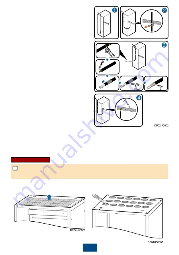
based on the 

Schematic Diagram

 delivered 

with the product and Appendix A.  

2. Route a cable into the cabinet and bind it to a 

nearby beam, as shown by (1) in the figure.  

3. Pull the cable to the copper bar to which the 

cable will be connected, determine the cable 
length, and label the cable, as shown by (2) in 
the figure.  
a. Mark a line where the cable is to be cut.  
b. Mark a line where the cable is to be 
stripped.  

4. Pull the labeled cable outside of the cabinet, 

and cut off the extra part at the marked line, as 
shown by (3) in the figure.  

5. Strip the cable at the marked line, and prepare 

terminals.  

6. Connect the input cables based on the 

Schematic Diagram

 delivered with the product, 

as shown by (4) in the figure.  
a. Route the input phase cables, N cable, and 
PE cable into the PDC.  
b. Connect the input N cable and PE cable to 
the corresponding N bar and PE bar.  
c. Connect the phase cables to the 
corresponding input terminals of phases L1, L2, 
and L3.  

7. Connect the output cables based on the 

Schematic Diagram

 delivered with the product, 

as shown by (4) in the figure.  
a. Connect one PE cable and one N cable from the PE bar and N bar inside the PDC to each 
load.  
b. Connect the output power cable from the wiring terminal of the PDC output terminal block to 
the corresponding load.  

8. Connect the signal cables based on the 

Schematic Diagram 

delivered with the product.  

9. Clear foreign matter inside the cabinet.  

1. (Optional) Remove the rodent-proof meshes or cut crosses in wire bushings in the top cabling 

scenario.  

Removing a rodent-proof mesh 

Cutting a cross in a wire bushing 

Routing Cables  

The figures are for reference only. The onsite objects prevail.  


NOTE

2. (Optional) Remove the rodent-proof meshes or cut crosses in wire bushings 

in the bottom cabling scenario.  

Содержание PDU8000 Series

Страница 1: ...HUAWEI TECHNOLOGIES CO LTD PDU8000 UPS PDC V1 0 Quick Installation Guide Issue 03 Date 2017 01 15 ...

Страница 2: ...n this document can be performed selectively based on the actual configurations Preparing Technical Documents 2 1 Technical Document Purpose Obtaining Method Remarks Installation Port Diagram Shows the installation port of the PDC Delivered with the product Schematic Diagram Shows the logic control relationship of circuit breakers in the PDC and the connection positions of input power cables outpu...

Страница 3: ...ion personnel and technical support personnel should prepare tools based on site requirements Prepare firestop putty for sealing cable holes after cable connection Huawei does not provide the firestop putty The customer needs to purchase it NOTE 2 Phase sequence meter Cable tie 3 Acceptance Guide After the equipment is delivered to the installation site representatives from the customer and Huawei...

Страница 4: ...n the figure 3 It is recommended that six people work together to move the PDC away from the pallet as shown by 2 and 3 in the figure 4 Adjust the PDC leveling feet using a wrench to ensure that all castors touch the ground 1 Optional Check whether the tiltwatch indicator on the carton has turned red If yes record the information and contact the equipment carrier and the local Huawei office immedi...

Страница 5: ...g washer and flat washer 1 M12 bolt 2 Spring washer 3 Flat washer 4 Expansion sleeve 5 Concrete floor Optional Installing the PDC on a Concrete Floor 4 9 Level the PDC using a level and an adjustable wrench 1 Wrench a leveling foot clockwise to elevate the cabinet or wrench a leveling foot counterclockwise to lower the cabinet The feet can be adjusted within a range of 0 8 mm 2 To prevent cabinet ...

Страница 6: ...cabinets need to be combined just partially tighten the bolts NOTE When cabinets need to be combined just partially tighten the bolts Optional Combining Cabinets 1 A connecting plate is initially secured by one screw Remove the screw from the column of the adjacent cabinet and use the screw to secure the connecting plate 2 Ensure that both the vertical deviation and the distances between cabinets ...

Страница 7: ...Terminals 1 Cable 2 Cord end terminal 3 Crimping tool Preparing Cord End Terminals 5 Cable Installation 6 Connection Method Connecting Cables 5 2 1 Ensure that all circuit breakers including upstream output circuit breakers are switched to OFF before connecting cables 2 DT and OT terminals must be coated with a heat shrink tubing 3 After cables are connected seal the cable inlet and outlet holes u...

Страница 8: ... cable into the PDC b Connect the input N cable and PE cable to the corresponding N bar and PE bar c Connect the phase cables to the corresponding input terminals of phases L1 L2 and L3 7 Connect the output cables based on the Schematic Diagram delivered with the product as shown by 4 in the figure a Connect one PE cable and one N cable from the PE bar and N bar inside the PDC to each load b Conne...

Страница 9: ...d reinstall them in the PDC 8 Optional Connecting Cables for the UPS Input and Output PDC 1 Connect the PE cable Secure one end of the ground cable to the ground bar inside the PDC and secure the other end to the ground grid or busbar of the equipment room 3 Connect the UPS input power cables NOTE 2 Connect the mains input power cables ...

Страница 10: ...er cables 5 Connect the mains output power cables for air conditioners and other loads a Optional MCCB output scenario b Optional Single phase output with a 1P output switch c Optional Single phase output with a 2P output switch 9 ...

Страница 11: ...MCB output scenario 6 Connect the UPS load output power cables a Optional MCCB output scenario b Optional Single phase output scenario with a 1P output switch c Optional Single phase output scenario with a 2P output switch 10 ...

Страница 12: ...e Secure one end of the ground cable to the ground bar inside the PDC and secure the other end to the ground grid or busbar of the equipment room 7 Connect signal cables d Optional Three phase MCB output scenario NOTE 11 2 Connect the mains input power cables 3 Connect the UPS input power cables ...

Страница 13: ...2 Optional Connecting Cables for the UPS Output PDC 1 Connect the PE cable as shown in the figure Secure one end of the ground cable to the ground bar inside the PDC and secure the other end to the ground grid or busbar of the equipment room 2 Connect the input power cables NOTE ...

Страница 14: ...on the cabinet exterior is intact Pass Fail 3 The cabinet door and lock work properly Pass Fail 4 All safety marks and warnings are correct clear and complete Pass Fail 5 There is no adhesive tape cable tie paper scrap or packing material around the cabinet Pass Fail No Check Item Check Result 1 All cables are connected correctly Pass Fail 2 Ground cables are securely connected Pass Fail 3 Power c...

Страница 15: ...ect using a phase sequence meter In the ATS input scenario check the phase sequences of both power inputs 5 Turn on the upstream switch of the SPD 6 Turn on the input circuit breaker of the PDC and check whether the voltage and frequency on the electric meter are normal 7 The PDC power on check is completed 1 Check cable connections and the mechanical performance Check that cables are connected co...

Страница 16: ...tch on other circuit breakers as shown in the figure Check that the insulation resistances of the power distribution devices and feed circuit are no less than 0 5 megohm After checking turn off all the circuit breakers 1 Check cable connections and the mechanical performance Check that cables are connected correctly outside the cabinet Check that all bolts are secured for inlet and outlet cables a...

Страница 17: ...m Terminal Bolt Specifications Recommended Torque N m Power input L N 160 50 DT M10 27 200 70 DT M12 47 250 95 DT M12 47 400 185 DT M12 47 630 2x185 DT M12 47 Power input PE 160 25 DT M10 27 200 35 DT M10 27 250 50 DT M10 27 400 95 DT M12 47 630 2x95 DT M12 47 AC output L 10 2 5 Cord end terminal insertion depth 8 12 mm 1 6 10 I 40 6 Cord end terminal insertion depth 8 12 mm 1 6 40 I 63 10 Cord en...

Страница 18: ...port huawei com Support Support E WeChat Google Play Scan here for technical support enterprise Scan here for technical support carrier Google Play Huawei App Store Huawei App Store Huawei Technologies Co Ltd Huawei Industrial Base Bantian Longgang Shenzhen 518129 People s Republic of China www huawei com Apple Store Apple Store ...

Отзывы: