background image


CONTENTS 


CONTENTS


CHAPTER 1.  PRODUCTS INTRODUCTION


......................................................................................................


1


1.1


B

RIEF


I

NSTRUCTIONS


FOR


M

ULTI

CHANNEL


T

HERMOCOUPLE


T

HERMOMETER

........................................................................


1


1.2


M

ULTI

CHANNEL


T

HERMOCOUPLE


T

HERMOMETERS


M

ODEL


N

UMBER


.................................................................................


2


1.3


S

INGLE

CHANNEL


LCD


DISPLAY


INSTRUCTIONS


(HE701

HE801)


.....................................................................................


2


1.4


T

WO

CHANNEL


LCD


DISPLAY


INSTRUCTIONS


(HE702

HE802)


........................................................................................


4


1.5


F

OUR

CHANNEL


LCD


DISPLAY


INSTRUCTIONS


(HE704

HE804)


.......................................................................................


5


1.6


I

NSTRUCTIONS


FOR


BUTTONS


FUNCTION


.........................................................................................................................


6


CHAPTER 2    INSTRUCTIONS FOR SOFTWARE OPERATION


.......................................................................


7


2.1


Q

UICK


S

TART


............................................................................................................................................................


7


2.2


C

ONNECTING


THE


T

HERMOMETER


D

ATA


L

OGGER


TO


PC


...................................................................................................


7


2.3


S

ETUP


THE


ATTRIBUTES


OF


THE


THERMOMETER


DATA


LOGGER


.............................................................................................


8


2.4


D

OWNLOAD


DATA


FROM


THE


THERMOMETER


DATA


LOGGER

.


..............................................................................................


9


2.5


D

ELETE


ALL


THE


LOGS


FROM


THE


THERMOMETER


DATA


LOGGER

.


.........................................................................................


9


2.6


D

ATA


L

ISTING


W

INDOW


...........................................................................................................................................


10


2.7


E

XPORTING


LOGS


FROM


THERMOMETER


DATA


LOGGER


....................................................................................................


11


2.8


F

ILE


L

IST


................................................................................................................................................................


11


Содержание HE70X Series

Страница 1: ...Operation Manual for HE70X 80X Series Multi channel thermocouple thermometer Huato Electronic Shenzhen Co LTD...

Страница 2: ...E802 4 1 5 FOUR CHANNEL LCD DISPLAY INSTRUCTIONS HE704 HE804 5 1 6 INSTRUCTIONS FOR BUTTONS FUNCTION 6 CHAPTER 2 INSTRUCTIONS FOR SOFTWARE OPERATION 7 2 1 QUICK START 7 2 2 CONNECTING THE THERMOMETER...

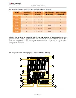
Страница 3: ...uato specialized Tespro software is easy to operate and quite convenient widely applied in industrial production fields food processing industry pharmaceutical industry and research testing fields as...

Страница 4: ...0 88 HE802 2 0 1 0 5 36000 88 HE804 4 0 1 0 5 36000 88 Notice The accuracy on the above table is only the accuracy for thermometer itself The precision in the practical applications has relation with...

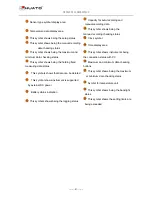
Страница 5: ...nd minimum data checking status This symbol shows instruments being the connection status with PC This symbol shows being the holding fixed measuring data status Maximum and minimum data checking butt...

Страница 6: ...ymbol shows that instrument is being connected with PC This symbol shows that the setting limits for channel 1 or channel 2 are being exceeded Display area for channel 1 and channel 2 This symbol show...

Страница 7: ...el 4 respectively This symbol shows that instrument is being connected with PC Data symbol for channel 1 channel 2 channel 3 and channel 4 This symbol shows setting limits are being exceeded This symb...

Страница 8: ...show DIS in the LCD corner means CAN T switch show En and press OK to delete auto recording data 4 SETUP TYPE lighting from K moving on one by one OK key to confirm the sensor type 1 Setup switch but...

Страница 9: ...sample and record and the LCD display is off Tespro cannot connect to the logger also 2 2 Connecting the Thermometer Data Logger to PC To connect the thermometer data logger to the computer follow th...

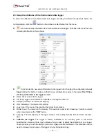
Страница 10: ...ame Gives a name to the logger z SN Every logger has a SN with 10 characters The length must be 10 z Sampling Interval The interval of sampling z LOG Intervals s The interval of recording z Logs Count...

Страница 11: ...ows will be displayed The graph display will be blank if there are not any logs Note Push left mouse button down and then move to select a rectangle area when the left mouse button is up the graph wil...

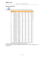
Страница 12: ...Click button on the toolbar and then the data listing window is shown below The data pane lists the data samples collected by the logging device The column width of each column is adjustable by using...

Страница 13: ...rt sample data to an Excel file z Export sample data to a text file z Export graph to a BMP file 2 8 File List The file list pane lists all the files in the directory Logfiles which is located in the...

Отзывы: