


CHECKING THE SWITCH
6 - 4
CHECKING THE SWITCH
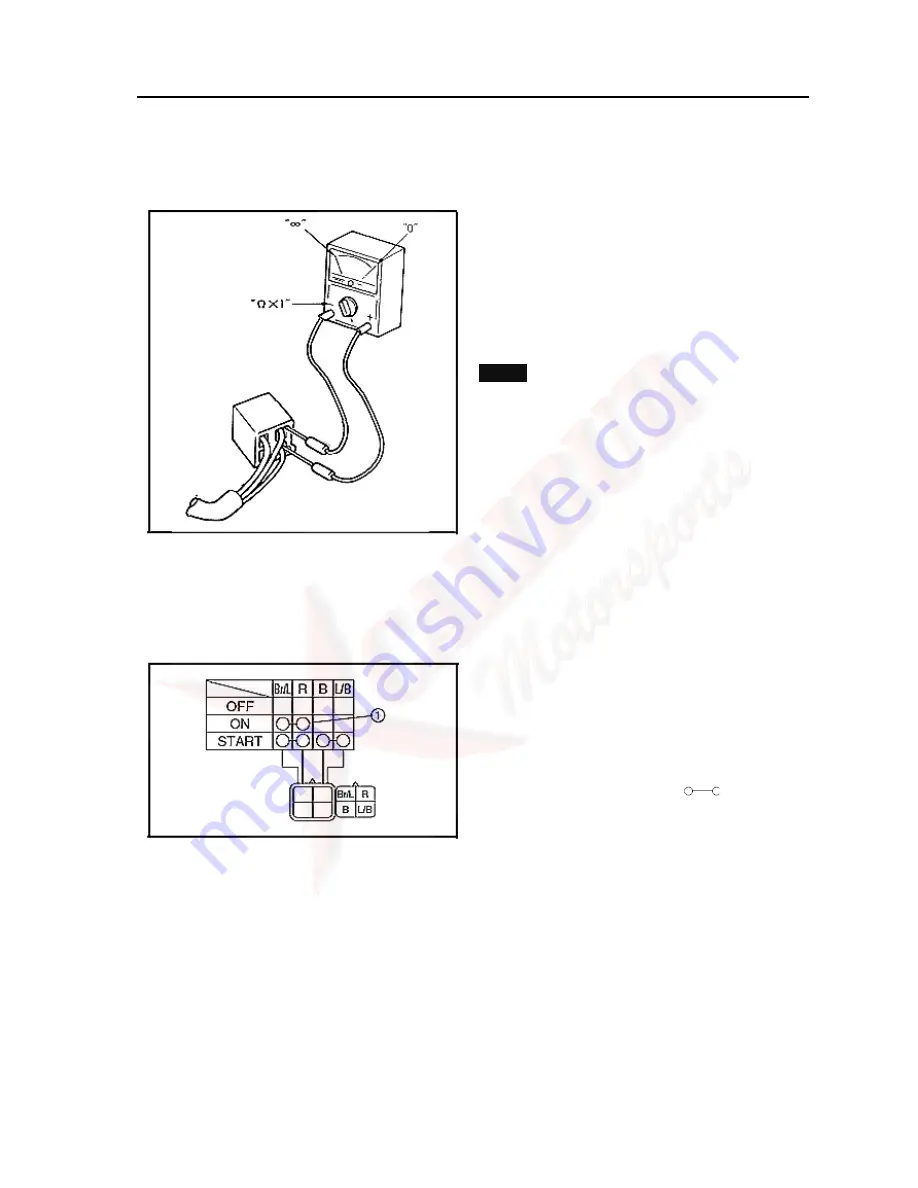
1.Checking the switch
Use a pocket tester to check the terminals for
continuity. If the continuity is faulty at any
point, replace the switch.
NOTE:
• Set the pocket tester to “0” before starting the
test.
• The pocket tester should be set to the “
Ω
× 1” .
range when testing the switch for continuity.
• Turn the switch on and off a few times when
checking it.
The terminal connections for switches (main
switch, light switch, etc.) are shown in a chart
similar to the one on the left. This chart shows
the switch positions in the column and the
switch lead colors in the top row.
For each switch position, “
”indicates
the terminals with continuity.
The example chart shows that:
① There is continuity between the“Brown/Blue
and Red” leads when the switch is set to“ON”.
Содержание UTV 700 2009
Страница 1: ...HUANSONG UTV 700 SERVICE MANUAL 2009 ...
Страница 96: ...GENERAL SPECIFICATIONS 2 23 HYDROGRAPHIC CHART Hydrographic chart Pressure splash ...
Страница 97: ...GENERAL SPECIFICATIONS 2 24 LUBRICATION OIL WAY ...
Страница 111: ...3 14 Oil gallery bolt 7 Nm 0 7 m kg 5 1 ft lb 12 Install console passenger seat driver seat Refer to SEATS in chapter 5 ...
Страница 146: ...CYLINDER HEAD 4 5 No Name part Qty Remarks 13 Thermo switch 1 1 For installation reverse the removal procedure ...
Страница 205: ...MIDDLE GEAR 4 64 Order Job Part Qty Remarks 11 Middle driven shaft 1 For installation reverse the removal procedure ...
Страница 246: ...5 31 BRAKE SYSTEM No Part Name Qty Remarks 26 Caliper piston seal 1 27 Bleed screw 1 ...
Страница 323: ...ELECTRIC STARTING SYSTEM 6 11 ELECTRIC STARTING SYSTEM CIRCUIT DIAGRAM Switch C D I Relay Motor Battery ...
Страница 330: ...CHARGING SYSTEM 6 18 CHARGING SYSTEM CIRCUIT DIAGRAM Ignition coil C D I Magneto Rectifier ...
Страница 333: ...LIGHTING SYSTEM 6 21 LIGHTING SYSTEM CIRCUIT DIAGRAM Flash Relay switch Rectifier Battery Light ...
Страница 337: ...SIGNALING SYSTEM 6 25 SIGNALING SYSTEM CIRCUIT DIAGRAM Flash Relay switch Rectifier Battery Light ...
Страница 348: ...COOLING SYSTEM 6 36 COOLING SYSTEM CIRCUIT DIAGRAM Temperature control switch fan motor Battery Circuit breaker switch ...
Страница 352: ...2WD 4WD SELECTING SYSTEM 6 40 2WD 4WD SELECTING SYSTEM CIRCUIT DIAGRAM Transfer Switch Relay Battery Motor Indicator ...


