lp-83 Rev. 006 Rel. 005 Date 12.18.17
17
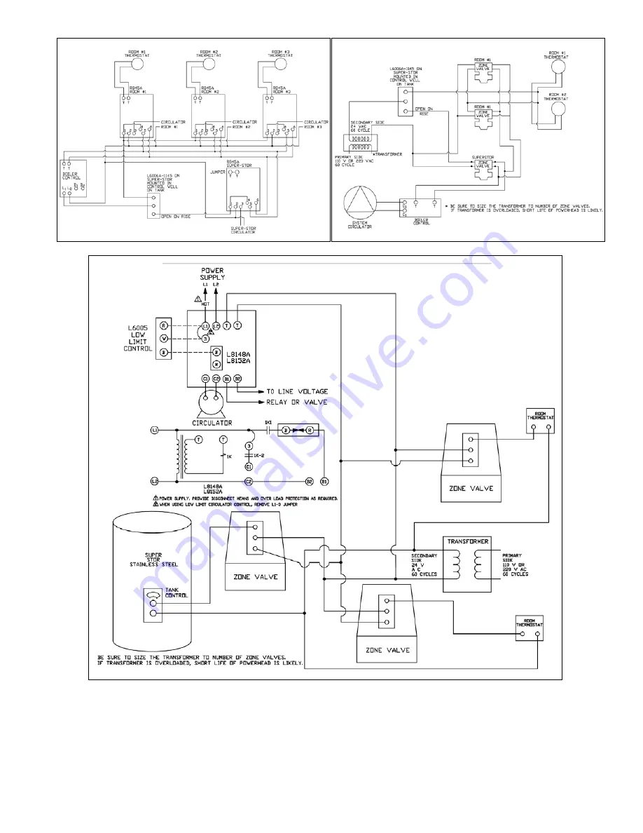
Figure 27 - Priority Zone with Circulators
Figure 28 - Priority Zone with Zone Valves
Figure 29 - Using L8148A or L8152A Cold Start Boiler Control with Zone Valves
Страница 1: ...ult in substantial property damage severe personal injury or death HTP reserves the right to make product changes or updates without notice and will not be held liable for typographical errors in literature The surfaces of these products contacted by potable consumable water contain less than 0 25 lead by weight as required by the Safe Drinking Water Act Section 1417 NOTE TO CONSUMER PLEASE KEEP A...
Страница 2: ... state provincial and national codes laws regulations and ordinances Part 1 General Safety Information This water heater is approved for indoor installation only and is not intended for use as a pool heater Clearance to combustible materials 0 top bottom sides and back Heater must have room for service 24 front 6 top and 0 sides are recommended service clearances A combustible door or removable pa...
Страница 3: ...warranty High heat sources sources generating heat 100o F 37o C or greater such as stove pipes space heaters etc may damage plastic components of the water heater as well as plastic vent pipe materials Such damages ARE NOT covered by warranty It is recommended to keep a minimum clearance of 8 from high heat sources Observe heat source manufacturer instructions as well as local state provincial and...
Страница 4: ...eater must be installed vertical on a level surface NOTE In the State of California the water heater must be braced anchored or strapped to avoid moving during an earthquake Contact local utilities for code requirements in your area Visit http www dsa dgs ca gov or call 1 916 445 8100 and request instructions However applicable local codes shall govern installation For residential water heaters of...
Страница 5: ...lp 83 Rev 006 Rel 005 Date 12 18 17 5 Figure 2 Dimensions ...
Страница 6: ...equired to achieve the listed first hour rating MODEL GROSS BOILER OUTPUT 140oF 90oF Δ T 127oF 77oF Δ T 115oF 65oF Δ T SSU 20 84 000 121 140 168 SSU 30 102 000 154 180 212 SSU 30LB 113 000 169 198 234 SSU 45 141 000 212 248 292 SSU 45C 215 000 314 367 414 SSU 60 174 000 266 311 370 SSU 60C 245 000 354 414 467 SSU 80 212 000 330 386 440 SSU 80C 331 000 490 573 647 SSU 119 269 999 423 495 564 SSU 11...
Страница 7: ...A 73 112 152 B 53 81 110 SSU 30 A 83 125 160 193 B 60 90 115 140 SSU 30LB A 84 128 166 213 B 60 92 120 154 SSU 45 A 94 138 180 210 242 B 68 100 130 152 175 SSU 60 A 221 244 251 258 266 287 305 B 160 176 181 186 192 207 220 SSU 80 A 297 305 314 367 424 489 503 B 216 223 230 269 311 359 370 SSU 119 A 333 384 444 457 470 543 627 645 B 216 251 290 335 345 399 460 474 C Reduced Boiler Input Sizing Guid...
Страница 8: ...he appliance it is still possible to have high TDS This water can be corrosive Consult local water treatment companies for other treatment solutions to reduce this affect NOTE To promote appliance service life it is strongly recommended to follow the maintenance procedures in this manual Part 3 Piping A Plumbing It is mandatory that all plumbing be done in accordance with federal local and state p...
Страница 9: ... and property damage serious injury or death may result RE INSPECTION OF T P RELIEF VALVES T P valves should be inspectedATLEASTONCEEVERYTHREEYEARS andreplacedif necessary by a licensed plumbing contractor or qualified service technician to ensure that the product has not been affected by corrosive water conditions and to ensure that the valve and discharged line have not been altered or tampered ...
Страница 10: ...3 11 77 12 24 12 7 13 1 10 GPM 10 25 11 1 11 95 12 8 13 66 12 GPM 11 3 13 2 14 1 15 16 14 GPM 15 3 16 4 17 5 18 6 19 8 Pressure Drop for Pipe Length of 1 1 4 Copper Six 90o Elbows and One Tee Pipe Size 20 30 40 50 60 20 GPM 10 9 11 7 12 6 13 4 14 3 22 GPM 14 15 16 17 18 24 GPM 16 2 17 5 18 8 20 1 21 5 28 GPM 20 4 22 23 6 25 2 26 8 Table 7 Pressure Drop through 1 and 1 1 4 Copper H Applications Fig...
Страница 11: ...ulators should have an integral flow check 4 Drains and check valve between heating appliance and water heater will assist in purging air from system 5 This drawing is meant to demonstrate system piping only The installer is responsible for all equipment and detailing required by local codes In Massachusetts you must install a vacuum relief valve per 248 CMR 6 Mixing valve application is optional ...
Страница 12: ... 3 All circulators should have an integral flow check 4 Drains and check valve between heating appliance and water heater will assist in purging air from system 5 This drawing is meant to demonstrate system piping only The installer is responsible for all equipment and detailing required by local codes In Massachusetts you must install a vacuum relief valve per 248 CMR 6 Mixing valve application i...
Страница 13: ...heck valve between heating appliance and water heater will assist in purging air from system 5 This drawing is meant to demonstrate system piping only The installer is responsible for all equipment and detailing required by local codes In Massachusetts you must install a vacuum relief valve per 248 CMR 6 Mixing valve application is optional but recommended to help prevent scalding See Part 3 Secti...
Страница 14: ...iler before starting any wiring procedures It is recommended that a disconnect switch be installed between the boiler control and the water heater Figure 16 Wiring with Circulators Figure 17 Wiring with Zone Valves C Wiring Diagrams CAUTION When wiring the water heater and controls be sure to label all wires to ease future maintenance Wiring errors can cause improper and dangerous operation CAUTIO...
Страница 15: ...g with Circulators R845A Relay Figure 19 Zoning with Circulators Using R8182D and DPST No Relay Required Figure 20 Zoning with Circulators Using L8124 A C and R845A Relay Figure 21 Zoning with Circulators Using L8124 A C and DPST Control No Relay Required ...
Страница 16: ...5A Relay Figure 24 Control with Built In DPST Switch No Relay Required Figure 22 Using L8148A or L8152A Cold Start Boiler Control with Circulators Figure 25 Zoning with Circulators Using L8124 E F and R845A Relay Figure 26 Zoning with Circulators Using L8124 E F and DPST No Relay Required ...
Страница 17: ...lp 83 Rev 006 Rel 005 Date 12 18 17 17 Figure 27 Priority Zone with Circulators Figure 28 Priority Zone with Zone Valves Figure 29 Using L8148A or L8152A Cold Start Boiler Control with Zone Valves ...
Страница 18: ...ng there are no leaks within the system flush the system to clear any soldering residue Many soldering fluxes contain Zinc Chloride which can corrode stainless steel Draw at least three times the volume of the water heater to properly flush the system 4 Initiate a call for hot water Ensure each zone valve or circulator operates only when its thermostat calls for heat Purge each zone of air to ensu...
Страница 19: ...e Replace if valve is blocked or does not operate properly NOTE TAKE CAUTION WHEN OPERATING RELIEF VALVE DISCHARGED WATER MAY PRESENT A SCALD RISK Drain Valve Open the drain valve and drain a few quarts of water from the bottom of the tank to flush any hard water deposits Replace if valve is blocked or does not operate properly NOTE TAKE CAUTION WHEN OPERATING DRAIN VALVE DRAINED WATER MAY PRESENT...
Страница 20: ...ir Trap in Loop Purge Air Not Enough Hot Water Zone valve restriction 1 full bore replace zone valve Circulator arrow reversed Reverse circulator Tank temperature too low Raise tank temperature Boiler temperature too low Raise boiler temperature Boiler sized too small Check sizing chart Tank sized too small Demand flow rate too high Install mixing valve Raise tank temperature Air trap in loop Purg...
Страница 21: ...rs utilized in heating applications that have been properly installed by qualified professionalsbaseduponthemanufacturer sinstallationinstructions G It is expressly agreed between HTP and the Owner that repair replacement or refund are the exclusive remedies of the Owner OWNER RESPONSIBILITIES The Owner or Qualified Installer Service Technician must 1 Have a relief valve bearing the listing marks ...
Страница 22: ...n warranty coverage by HTP claims department personnel All alleged defective or malfunctioning components must be returned to HTP via the local distribution channels where original purchase was made NOTE Any components or heaters returned to HTP for warranty analysis will become the property of HTP and will not be returned even if credit is denied If all warranty conditions are satisfied HTP will ...
Страница 23: ...te of Installation Installation Address Product Name Serial Number s Comments Installer s Code Name Installers Phone Number Signed by Installer Signed by Customer IMPORTANT Customer Please only sign after the qualified installer service technician has fully reviewed the installation safety proper operation and maintenance of the system If the system has any problems please call the qualified insta...