background image


Ver 1.1 6/30/14 
 

Rear Board & Function………………………………………………………………………..                                                                     


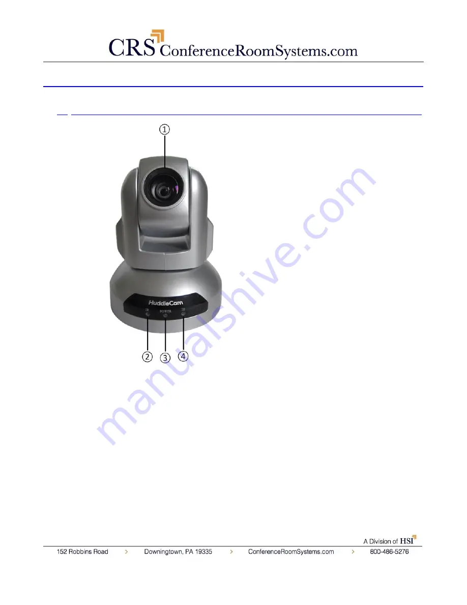
1.


Front View…………………………………………………………………………………….


1.


Lens


10x Optical Zoom. 

2.


IR Receiver


To receive IR remote controller signal.


3.


Power LED


Blue LED blinks when unit is powered

Orange LED blinks for Stand-By status.


4.


IR Receiver


To receive IR remote controller signal.


Содержание HuddleCam-HD 10X

Страница 1: ......

Страница 2: ...the camera away from strong electromagnetic sources Do not aim the camera at bright light sources e g bright lights the sun etc for extended periods of time Do not clean the camera with any active chemicals or corrosive detergents Do not disassemble the camera or any of the camera s components If problems arise please contact your authorized dealer After long term operation moving components can w...

Страница 3: ...Configuration Dip Switch Pin 7 TTL Signal Baud Rate 9600bps Power Supply Interface DC 12V Socket Electrical Power Supply Adapter 12V DC 2A Input Voltage 12V DC 10 5 14V DC Input Power 24W MAX Structure Material Aluminum Plastic Dimensions W x H x D 4 88 in 123 952mm x 5 75 in 146 05mm x 4 75 in 120 65mm Mass 1 46 lbs 0 67kg Working Environment Indoor Operating Temperature 32ºF 0ºC to 113ºF 45ºC St...

Страница 4: ...ion 1 Front View 1 Lens 10x Optical Zoom 2 IR Receiver To receive IR remote controller signal 3 Power LED Blue LED blinks when unit is powered Orange LED blinks for Stand By status 4 IR Receiver To receive IR remote controller signal ...

Страница 5: ...o receive IR remote controller signals 7 VISCA IN Port For hard wired remote control from a 3rd party PC joystick etc 8 VISCA Out Port RS485 Used for daisy chaining multiple cameras for RS 232 RS 485 control 9 USB 2 0 Interface For connection to PC USB 2 0 port Will also function in a USB 3 0 port as USB 2 0 device ...

Страница 6: ... 1 1 6 30 14 3 Bottom View 1 Tripod Will accept 1 4 20 bolt from 3rd party tripod wall or ceiling mount using included tripod adapter 2 Dip Switches Used for selecting serial and IR communications settings ...

Страница 7: ...DIP 7 1 ON OFF OFF OFF OFF OFF OFF 2 OFF ON OFF OFF OFF OFF OFF 3 OFF OFF ON OFF OFF OFF OFF 4 OFF OFF OFF ON OFF OFF OFF 5 OFF OFF OFF OFF ON OFF OFF 6 OFF OFF OFF OFF OFF ON OFF 7 OFF OFF OFF OFF OFF OFF ON Notes 1 Broadcast address If the Joystick is 255 all dip switches on any Camera can be controlled by any address 2 Test Address If the dome camera address is 0 all dip switches off any addres...

Страница 8: ...ing Address Table IR Remote Address SW2 Switch State 4 5 DIP 4 DIP 5 0 OFF Def OFF Def 1 OFF ON 2 ON OFF 3 ON ON SW2 DIP 6 IR Output IR Out SW2 DIP 6 Disabled OFF Def Enabled ON Baud Rate SW2 DIP 1 Communication Mode SW2 DIP 2 Communication Protocol SW2 DIP 3 9600bps OFF Def RS 232 OFF Def VISCA OFF Def 38400bps ON RS 485 ON PELCO D ON ...

Страница 9: ...Ver 1 1 6 30 14 Cable Connection Info VISCA RS 232C IN Reference VISCA RS 232C Out Reference ...

Страница 10: ... visible on the screen The Dome OSD Menu is as follows not applicable see note above Pan Speed Default Value 20 Set speed of Pan motor Range 1 63 Tilt Speed Default Value 20 Set speed of Pan motor Range 1 63 Scan Speed Auto Pan Mode Default Value 6 Set speed of boundary scan Range 1 63 Tour Path uses presets Default Value 1 Select desired tour path Range 1 4 Tour Dwell Default Value 5 Set duration...

Страница 11: ...R Noise Reduction Default Value 3 Adjustable Value 0 5 WB White Balance Default Value Auto Auto Manual Outdoor Indoor One Push ATW Manual Settings R GAIN Red Gain Default Value 206 Adjustable Scope 0 255 B GAIN Blue Gain Default Value 150 Adjustable Scope 0 255 AE Auto Exposure Default Value Auto Auto Manual Manual Settings SHUTTER Default Value 1 1 Shutter Speed Range 1 1 1 10000 IRIS Default Val...

Страница 12: ...in out Control Zone Zoom in quickly Zoom out quickly 5 Pan Tilt Controller Move Up Move Down Move Left Move Right Auto Pan 6 Additional Function Zone Freeze Image Freeze BL Back light Compensation WB White Balance AE Auto Exposure D Zoom Digital Zoom HDMI Swap to HDMI video output DVI Swap to DVI video output Format Swap between different formats 7 Power Supply Switch Switch for turning camera on ...

Страница 13: ...presets Rev Enable image flip for ceiling mounting Connection Instructions 1 Connect included Power Supply to the camera 2 Wait for camera to come to Home Position 3 Connect included USB 2 0 cable to camera and USB 2 0 port of PC 4 Select and configure camera in your software of choice NOTE Failure to follow this sequence may result in no connection to PC Care Of The Unit Remove dust or dirt on th...

Страница 14: ...want to use the camera on an incline make sure the angle is less than 15 degrees to ensure that the camera s pan and tilt mechanism operates normally Tripod Installation When using the HuddleCam with a tripod screw the tripod to the bottom of the camera The tripod screw must fit below specifications Note Tripod must stand on a level surface ...

Страница 15: ...Ver 1 1 6 30 14 To fix the tripod mount to the bottom of the camera use the supplied screws to hold it in place Then screw the tripod to the tripod bracket ...

Страница 16: ...Ver 1 1 6 30 14 Wall and Ceiling Mount ...

Страница 17: ...d on the screen Retry after exiting the menu Pan tilt or zoom range limit was reached Try to pan tilt zoom in the other direction Remote control not working The camera select button on the remote control is not set to match the IR address set on the camera dip switch Choose the correct IR select number to match camera settings Camera cannot be controlled via VISCA The connection between the PC and...

Страница 18: ......

Страница 19: ......

Страница 20: ......

Отзывы: