


Contents
Illustrated parts catalog..........................................................................5
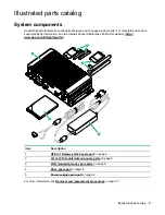
System components......................................................................................................................5
HPE IoT Gateway GL20 spare part................................................................................... 6
3G or LTE module/antenna spare parts ............................................................................ 6
WiFi module/antenna spare parts ..................................................................................... 6
Drive spare part..................................................................................................................6
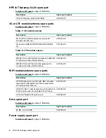
Power supply spare part.................................................................................................... 6
Customer self repair............................................................................... 8
Removal and replacement procedures............................................... 17
Required tools.............................................................................................................................17
Safety considerations..................................................................................................................17
Preventing electrostatic discharge................................................................................... 17
Symbols on equipment.....................................................................................................17
System warnings and cautions........................................................................................ 18
Preparing to remove or replace components..............................................................................18
Powering down the gateway............................................................................................ 19
Dismounting the gateway.................................................................................................19
Removing the WiFi and LTE combo antennas................................................................. 20
Removing the bottom access panel................................................................................. 20
Removing and replacing a drive................................................................................................. 21
Removing and replacing a 3G/LTE module................................................................................ 22
Removing and replacing a half-length WiFi/WLAN module........................................................ 23
Removing and replacing a full-length WiFi/WLAN module......................................................... 24
Removing and replacing an antenna.......................................................................................... 25
Removing and replacing a power supply.................................................................................... 26
Component identification.....................................................................27
Front panel components............................................................................................................. 27
Front panel LEDs and buttons.................................................................................................... 27
Rear panel components..............................................................................................................28
Expansion board components.................................................................................................... 29
Antenna connector locations.......................................................................................................29
Connector pin assignments........................................................................................................ 30
RJ-45 LAN connector pin assignments............................................................................30
HDMI connector pin assignments.................................................................................... 30
USB connector pin assignments...................................................................................... 31
Digital I/O connector pin assignments..............................................................................32
VGA D-SUB connector pin assignments..........................................................................32
System audio connector pin assignments........................................................................33
Optional I/O serial port pin assignments.......................................................................... 33
Power input connector pin assignments.......................................................................... 34
Power Over Ethernet connector pin assignments............................................................34
Contents
3
Содержание Edgeline EL20
Страница 7: ...Description Spare part number GL20 power supply with cord 847060 001 Illustrated parts catalog 7...
Страница 14: ...14 Customer self repair...
Страница 15: ...Customer self repair 15...
Страница 16: ...16 Customer self repair...
Страница 35: ...Pin Assignment 1 Rx DC 2 RX DC 3 Tx DC 4 Unused 5 Unused 6 Tx DC 7 Unused 8 Unused Component identification 35...
Страница 51: ...Extensible Host Controller Interface Acronyms and abbreviations 51...