HPE Edgeline EL20 Скачать руководство пользователя страница 18


This symbol indicates the presence of a hot surface or hot component. If this surface is
contacted, the potential for injury exists.

WARNING:

 To reduce the risk of injury from a hot component, allow the surface to cool

before touching.


2.72 kg

6.0 lb

This symbol indicates that the component exceeds the recommended weight for one
individual to handle safely.

WARNING:

  To reduce the risk of personal injury or damage to the equipment,

observe local occupational health and safety requirements and guidelines for manual
material handling.

These symbols, on power supplies or systems, indicate that the equipment is supplied
by multiple sources of power.

WARNING:

 To reduce the risk of injury from electric shock, remove all power cords to

disconnect power from the system completely.

System warnings and cautions

Before installing a gateway, be sure that you understand the following warnings and cautions.

WARNING:

To reduce the risk of electric shock or damage to the equipment:

• Do not disable the power cord grounding plug. The grounding plug is an important safety feature.
• Plug the power cord into a grounded (earthed) electrical outlet that is easily accessible at all

times.

• Unplug the power cord from the power supply to disconnect power to the equipment.
• Do not route the power cord where it can be walked on or pinched by items placed against it.

Pay particular attention to the plug, electrical outlet, and the point where the cord extends from
the gateway.

WARNING:

To reduce the risk of personal injury from hot surfaces, allow the drives and the internal system
components to cool before touching them.

CAUTION:

Do not operate the gateway for long periods with the access panel open or removed. Operating the
gateway in this manner results in improper airflow and improper cooling that can lead to thermal
damage.

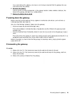
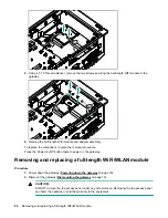
Preparing to remove or replace components

Before performing certain service procedures and to access some components, you must perform one or
more of the following procedures.

Procedure

1. Power down the gateway

.

18

 System warnings and cautions

Содержание Edgeline EL20

Страница 1: ...bes identification and maintenance procedures diagnostic tools specifications and requirements for hardware components and software This guide is for an experienced service technician Hewlett Packard...

Страница 2: ...control over and is not responsible for information outside the Hewlett Packard Enterprise website Acknowledgments Intel Itanium Pentium Intel Inside and the Intel Inside logo are trademarks of Intel...

Страница 3: ...ive 21 Removing and replacing a 3G LTE module 22 Removing and replacing a half length WiFi WLAN module 23 Removing and replacing a full length WiFi WLAN module 24 Removing and replacing an antenna 25...

Страница 4: ...ATA Configuration 40 Intel R Rapid Start Technology 40 PCH FW Configuration 40 USB Configuration 40 Embedded Controller Configuration 41 IT8768 Super IO Configuration 41 Serial Port Console Redirectio...

Страница 5: ...d Enterprise PartSurfer website http www hpe com info partssurfer 1 2 3 4 5 Item Description 1 HPE IoT Gateway GL20 spare part on page 6 2 3G or LTE module antenna spare parts on page 6 3 WiFi module...

Страница 6: ...ncludes WAN antenna 847052 001 WWAN LTE mini PCIe Wide Temperature APJ module kit includes WAN antenna 847055 001 WiFi module antenna spare parts Customer self repair on page 8 Mandatory Description S...

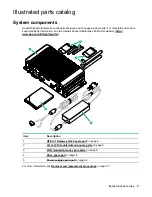
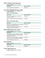
Страница 7: ...Description Spare part number GL20 power supply with cord 847060 001 Illustrated parts catalog 7...

Страница 8: ...ckard Enterprise you must ship the defective part back to Hewlett Packard Enterprise within a defined period of time normally five 5 business days The defective part must be returned with the associat...

Страница 9: ...lient est obligatoire Si vous demandez Hewlett Packard Enterprise de remplacer ces pi ces les co ts de d placement et main d uvre du service vous seront factur s Riparazione da parte del cliente Per a...

Страница 10: ...hrt und Arbeitskosten f r diesen Service berechnet Optional Teile f r die das Customer Self Repair Verfahren optional ist Diese Teile sind auch f r Customer Self Repair ausgelegt Wenn Sie jedoch den A...

Страница 11: ...e la sustituci n de estos componentes Dichos componentes se identifican con la palabra No en el cat logo ilustrado de componentes Seg n la disponibilidad y la situaci n geogr fica los componentes CSR...

Страница 12: ...ise vermeldt in de documentatie bij het vervangende CSR onderdeel of het defecte onderdeel aan Hewlett Packard Enterprise moet worden geretourneerd Als het defecte onderdeel aan Hewlett Packard Enterp...

Страница 13: ...os com a pe a CSR de reposi o se a pe a com defeito deve ser devolvida Hewlett Packard Enterprise Nos casos em que isso for necess rio preciso enviar a pe a com defeito Hewlett Packard Enterprise voc...

Страница 14: ...14 Customer self repair...

Страница 15: ...Customer self repair 15...

Страница 16: ...16 Customer self repair...

Страница 17: ...rom their containers Avoid touching pins leads or circuitry Always be properly grounded when touching a static sensitive component or assembly Symbols on equipment The following symbols might be found...

Страница 18: ...f electric shock or damage to the equipment Do not disable the power cord grounding plug The grounding plug is an important safety feature Plug the power cord into a grounded earthed electrical outlet...

Страница 19: ...initiates a controlled shutdown of applications and the OS before the gateway enters standby mode Press and hold the Power On Standby button for more than 4 seconds to force the gateway to power down...

Страница 20: ...9 3 Locate the correct antenna cable to remove For antenna connector locations see Antenna connector locations on page 29 4 Remove the antenna cable from the gateway Press the Power On Off button twic...

Страница 21: ...on the side of the gateway 4 Loosen the two thumbscrews securing the drive tray to the gateway and then remove the drive tray NOTE Observe the orientation of the drive within the drive tray before you...

Страница 22: ...n page 19 2 Dismount the gateway Dismounting the gateway on page 19 CAUTION DO NOT remove the top access panel under any circumstance Removing the top access panel can harm the heatsink or void the wa...

Страница 23: ...acing a half length WiFi WLAN module Procedure 1 Power down the gateway Powering down the gateway on page 19 2 Dismount the gateway Dismounting the gateway on page 19 CAUTION DO NOT remove the top acc...

Страница 24: ...the Power On Off button twice to power on the gateway Removing and replacing a full length WiFi WLAN module Procedure 1 Power down the gateway Powering down the gateway on page 19 2 Dismount the gatew...

Страница 25: ...screws securing the full length WiFi module to the gateway WLAN W L A N 6 Remove the full length WiFi module To replace the component reverse the removal procedure Press the Power On Off button twice...

Страница 26: ...placing a power supply Procedure 1 Power down the gateway Powering down the gateway on page 19 2 Disconnect the power cord from the power connector at the rear of the gateway To replace the component...

Страница 27: ...4 5 6 Item Description 1 USB 2 0 connectors 2 2 HDMI connector 3 Drive bay 4 VGA connector 5 LAN connectors 2 6 Optional I O serial connectors RS 232 or RS 422 485 2 7 USB 3 0 connectors 2 Front pane...

Страница 28: ...white System on Off System off 1 The reset button is indented and you might need a tool such as a pin to press it Rear panel components PE POE1 POE2 POE3 ANT ANT System ANT POE4 PIN 0 5 DI PIN 6 7 DO...

Страница 29: ...AN module slots Antenna connector locations PE POE1 POE2 POE3 ANT ANT System ANT POE4 PIN 0 5 DI PIN 6 7 DO PIN 8 9 GND 1 2 3 3 4 5 6 7 8 9 V V HDMI VGA LAN1 LAN2 PWR Optional I O 1 Optional I O 2 SSD...

Страница 30: ...5 BI_DC GHz 6 RX 10 100 BI_DB GHz 7 BI_DD GHz 8 BI_DD GHz 1 NC if present means that there is no connection HDMI connector pin assignments The HDMI link supports resolutions of up to 4096 x 2304 at 24...

Страница 31: ...a3 13 NC 14 NC 15 SCL AUX_CH 16 SDA GND 17 DDC GND AUX_CH 18 5 V Hot plug detect 19 Hot plug detect return 20 DP_PWR USB connector pin assignments The USB interface supports plug and play The upper US...

Страница 32: ...TX 9 5 V 10 D 11 D 12 Ground Digital I O connector pin assignments 0 1 2 3 4 5 6 7 8 9 DI DO GND Pin Assignment 0 to 5 Digital input 6 and 7 Digital output 8 and 9 Ground VGA D SUB connector pin assig...

Страница 33: ...onnector pin assignments Pin Assignment 1 Mic 2 Line in 3 Line out Optional I O serial port pin assignments The two optional I O serial ports are compatible with RS 232 RS 422 and RS 485 signals 1 6 7...

Страница 34: ...3 Pin Assignment 1 V 2 V 3 Unassigned Power Over Ethernet connector pin assignments There are four 10 100 PoE ports Four ports support up to 7 W full load at IEEE802 3af Class 2 Two ports support up t...

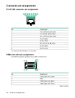
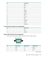
Страница 35: ...Pin Assignment 1 Rx DC 2 RX DC 3 Tx DC 4 Unused 5 Unused 6 Tx DC 7 Unused 8 Unused Component identification 35...

Страница 36: ...he system BIOS The system BIOS also has options for restoring default configurations and resetting the system The setup information is stored in the battery backed CMOS therefore it retains the setup...

Страница 37: ...fy the setting selected 6 Do one of the following Press the F4 key to save the new setting and exit Press the Esc key to exit without saving Main tab Setting the System Date and System Time Procedure...

Страница 38: ...g Advanced tab The Advanced tab has the following menu options PCI Subsystem Settings ACPI Settings S5 RTC Wake Settings CPU Configuration SATA Configuration Intel R Rapid Start Technology PCH FW Conf...

Страница 39: ...Link Status register Values range from 10 to 10 000 Unpopulated Links Enables user to set to Disable Link in order to save power by unpopulating the PCI Express links Restore PCIE Registers Enables us...

Страница 40: ...displayed with the following information and options Software Preserve Port Enables or disables the SATA port Hot Plug Enables or disables the hot plug External SATA Enables or disables the external...

Страница 41: ...imer IT8768 Super IO Configuration The Super Chip configuration details are displayed including Serial Port 1 Configuration Enables user to configure serial port 1 Serial Port 2 Configuration Enables...

Страница 42: ...PCI express root port 1 2 3 6 setting USB Configuration Displays configuration of USB functions USB Precondition Enables or disables USB precondition Precondition work on the USB host controller and r...

Страница 43: ...er to select DVMT total memory size Gfx Lower Power Mode Available for SFF only Enables user to lower the graphics power mode LCD Control Primary IGFX Boot Display Enables user to select boot display...

Страница 44: ...policy Enables user to control the execution of UEFI and legacy Video Option ROM Other PCI device ROM priority Enables user to define which Option ROM to launch for PCI devices other than network mass...

Страница 45: ...ot Variables Enables user to store the content of each secure boot variable to file system root folder Platform Key Enables user to delete or set new Platform Key Key Exchange Key Enables user to dele...

Страница 46: ...s user to discard changes made so far to any of the options Restore Defaults Enables user to restore load default values for all the options Save as User Defaults Enables user to save the changes made...

Страница 47: ...condensing 95 relative humidity at 40 C 1 All temperature ratings shown are for sea level An altitude derating of 1 0 C per 304 8 m 1 8 F per 1000 ft to 3048 m 10 000 ft is applicable No direct sunlig...

Страница 48: ...19 0 V Rated output current 7 89 A Power consumption specifications Specification Value Typical 70 W with full load on PoE1 Maximum 35 W 1 The four port PoE power budget is 30 W in total Each PoE port...

Страница 49: ...BS BIOS Boot Specification CPUID CPU identification CSM Compatibility Support Module cTDP configurable Thermal Design Power DMI Desktop Management Interface DVMT dynamic video memory technology EHCI E...

Страница 50: ...ent Interconnect Express PCIe Peripheral Component Interconnect Express SMI System Management Interrupt PoE Power over Ethernet PTT Push to Talk PXE preboot execution environment RTC real time clock T...

Страница 51: ...Extensible Host Controller Interface Acronyms and abbreviations 51...

Страница 52: ...gestions or comments to Documentation Feedback docsfeedback hpe com When submitting your feedback include the document title part number edition and publication date located on the front cover of the...

Отзывы: