


•
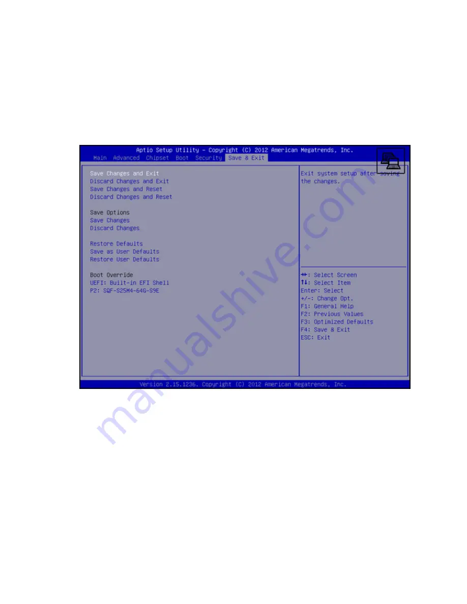
Save Changes and Exit
—Enables user to exit system setup after saving changes
•
Discard Changes and Exit
—Enables user to exit system setup without saving any changes
•
Save Changes and Reset
—Enables user to reset the system after saving the changes
•
Discard Changes and Reset
—Enables user to reset the system without saving the changes
•
Save Changes
—Enables user to save changes made so far to any of the options
•
Discard Changes
—Enables user to discard changes made so far to any of the options
•
Restore Defaults
—Enables user to restore/load default values for all the options
•
Save as User Defaults
—Enables user to save the changes made so far as user defaults
•
Restore User Defaults
—Enables user to restore the user defaults to all the options
•
Boot Override
—Enables user to override your boot priority
Software and configuration utilities
47


