background image


English

33

2   How to Install Accessories In Your PC

Installing an Upgrade/Overdrive Processor

2   

Install

ing Acc

e

sso

rie

s

3

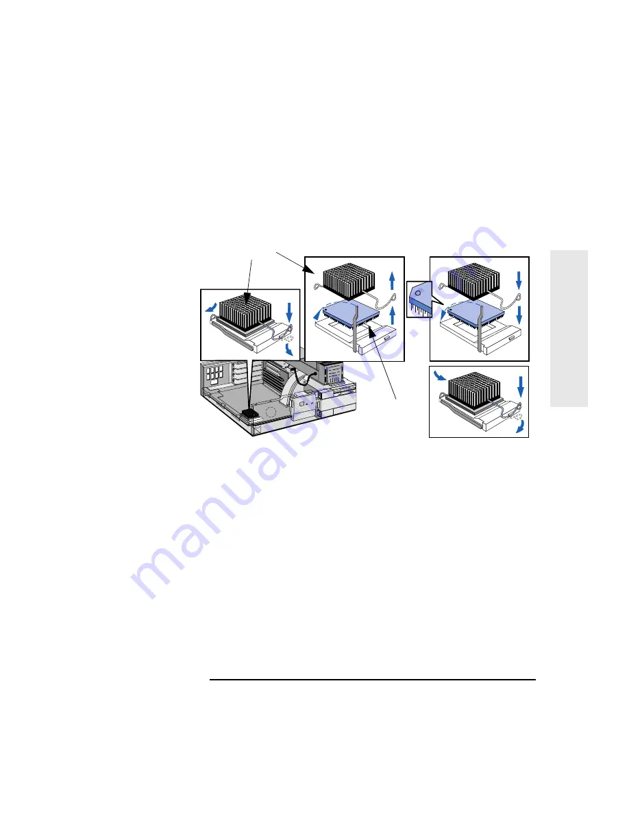
If the heatsink is not directly attached to the processor, unclip and 
remove the heatsink.

4

Raise the lever on the socket to unlock the processor and lift out the 
processor.

5

To install the new processor:

a

Locate the corner marker (a dot or notch and a ‘broken’ corner) 
on the processor

b

Align the corner marker on the processor with the top-left corner 
of the socket (see the previous diagram) and place the processor 
into the socket.

c

Close the lever to lock the processor into place.

d

If your processor operates at 120 MHz or greater and has a 
separate heat sink, add a drop of ‘thermal compound’ to the top 
of the processor.

e

Replace the heatsink and fasten the clip (if the heatsink is not 
already directly attached to the processor).

Heat Sink

Processor

Содержание VECTRA VE

Страница 1: ...HP Vectra VE User s Guide ...

Страница 2: ...on that is protected by copyright All rights are reserved No part of this document may be photocopied reproduced or translated to another language without the prior written consent of Hewlett Packard Company Centronics is a registered trademark of Centronics Data Computer Corporation Microsoft and MS DOS are registered trademarks of Microsoft Corporation Microsoft Windows and Windows 95 are produc...

Страница 3: ...User s Guide ...

Страница 4: ...s use a power cord with a properly grounded plug such as the one provided with this equipment or one in compliance with your national regulations This PC is disconnected from the power by removing the power cord from the power outlet This means the PC must be located close to a power outlet that is easily accessible For your safety never remove the PC s cover without first removing the power cord ...

Страница 5: ...ows 95 users open the Start menu in the task bar and choose Help Then double click on the help topic Working in Comfort For Windows for Workgroups users open the Program Manager open the program group HPUtils and double click on HP User Tools icon Then click on Working in Comfort in the page tagged Information For DOS users refer to the Working in Comfort booklet ...

Страница 6: ...Important Safety Information vi Francais ...

Страница 7: ... Your PC s Hardware Control Panel 6 Starting and Stopping Your PC 7 Starting Your PC for the First Time 7 Starting Your PC 7 Stopping Your PC and HP Off 7 Asset Tracking 9 PC Identification Tattoo String 9 PC Serial Number 9 Protecting Your PC 10 Setting an Administrator and a User Password 10 Using Power Management 11 Desktop Management Interface DMI 11 HP Dynamic Video 11 Additional Information ...

Страница 8: ...umber of Displayed Colors 20 Installing Mass Storage Devices 21 Connecting IDE Devices 21 Configuring an IDE Device After Installation 22 Installing a Flexible Disk Drive or a CD ROM Drive in the Middle Shelf 23 Installing an IDE Hard Disk Drive in the Rear Shelf 24 Installing an IDE Hard Disk Drive in the Bottom Shelf 26 Installing a Tape Drive in the Bottom Shelf 28 Installing a BNC Coax Adapter...

Страница 9: ...p 50 If a POST Error Message is Displayed 50 If Your PC Has a Hardware Problem 52 Display Does Not Work Properly 52 If Your Keyboard Does Not Work 53 If Your Mouse Does Not Work 53 If Your Printer Does Not Work 54 If the Flexible Disk Drive Does Not Work 55 If the Hard Disk Does Not Work 55 If the CD ROM Drive Has a Problem 56 If an Accessory Board Does Not Work 57 If Your PC Has a Software Proble...

Страница 10: ... J 7 65 Cache Jumper J6 65 Multipurpose Switch SW1 66 Power on Spacebar Feature Jumper JP4 66 6 Hewlett Packard Support and Information Services Introduction 68 Your HP Authorized Reseller 69 HP SupportPack 69 HP Support Assistant CD ROM 70 Hewlett Packard Information Services 71 HP Forum on CompuServe 71 HP Forum on America Online 72 HP BBS Library 73 HP World Wide Web Site 73 HP FAXback on Deman...

Страница 11: ...mated Support Directory 74 Ordering Drivers and BIOS on Diskette 75 Hewlett Packard Telephone Support 76 Lifeline Telephone Support 77 HP Network Phone in Support Service NPS 78 Summary 79 Hewlett Packard Marketing Headquarters 80 Glossary 81 ...

Страница 12: ...xii English ...

Страница 13: ...1 Setting Up and Using 1 Setting Up and Using Your PC ...

Страница 14: ...ectors are easily accessible 4 Place the display on top of the computer If you have a large display place it next to the computer Refer to the display s manual for information about the display Operating System Your PC s operating system is preloaded on your PC s hard disk Installation Tools No tools are required to set up your PC However if you plan to install a disk drive or an accessory board i...

Страница 15: ...ors are shaped to go in one way only Tighten the display cable attachment screws If you have a printer connect the printer cable to the back of the computer and tighten the attachment screws Use the connector labeled Parallel 25 pin parallel connector for a parallel device Serial A 9 pin serial connector for a serial device Serial B 9 pin serial connector for a second serial device Mouse Keyboard ...

Страница 16: ...power cord and the computer s power cord to a grounded outlet WARNING For your safety always connect the equipment to a grounded wall outlet Always use a power cord with a properly grounded plug such as the one provided with this equipment or one in compliance with your national regulations This PC is disconnected from the power by removing the power cord from the power outlet This means the PC mu...

Страница 17: ...k cable to the RJ 45 UTP Unshielded Twisted Pair LAN connector To enable your network connection refer to the Integrated Network Interface Submenu in the Configuration Menu of the HP Setup program You can find additional information in the online Network Administrator s Guide NOTE If you need a BNC Coax connector to connect to the network you can install an optional BNC coax adapter order HP D3979...

Страница 18: ...Button Press this button to turn the power on or off to your PC Hard Disk Activity Light This light glows flickers when your hard disk drive is being accessed The hard disk activity light only works if you have an IDE hard disk drive which comes with your Vectra PC If you replace this drive with a SCSI hard disk drive this light will not work Power On Off Power on Status Light Hard Disk Activity L...

Страница 19: ...s press the power button on the front panel press the space bar When you switch on the computer the computer carries out the Power On Self Test POST while the Vectra logo is displayed If you wish to view the POST details press to get the HP Summary Screen If there is an error in the POST the error will automatically be displayed 3 If you have set a password in the PC s Setup program the password p...

Страница 20: ...ff tab and click the HP Off option 3 Set a time for the HP Off time out This is the amount of time you are given in seconds to cancel the shut down sequence Try Out HP Off If you want to try out HP Off do the following 1 Enable HP Off 2 Create a new file and do not save it 3 Press the on off button the PC front panel A dialog box with the message About to shut down Windows appears on the screen Yo...

Страница 21: ...r choice the very first time you start your PC The message appears in the following places The HP Summary Screen HP Summary Screen on page 42 In the PC Identification Control Panel To Modify the Tattoo To modify the tattoo string double click the PC Identification icon in the Control Panel PC Serial Number The PC serial number appears in the HP Summary Screen HP Summary Screen on page 42 and is ac...

Страница 22: ...ram by using the User Password you will be restricted in your ability to change setup items If you enter the Setup program with an Administrator Password you will have no restrictions Setting an Administrator and a User Password To set an administrator or a user password 1 Start the Setup Program Refer to Using the Setup Program on page 44 2 Select the Security menu group 3 Select the Administrato...

Страница 23: ...Suspend mode In case of network disconnects in Suspend mode try using Stand By mode If you still get disconnects disable power management Desktop Management Interface DMI If your PC has Windows 95 or Windows for Workgroups it is delivered with DMI software This allows management information systems MIS personnel to manage up to 300 features on the PC remotely Double click on the DMI on line refere...

Страница 24: ...ollowing topics New features what is new and special about your PC Using your PC simple how to use guidelines about using your PC Working in comfort guidance on ergonomic issues Inside your PC describes the basic parts of your PC how to upgrade and how to optimize performance HP support similar to chapter 5 in this User s Guide In Windows for Workgroups For Windows for Workgroups users open the Pr...

Страница 25: ...2 Installing Accessories 2 How to Install Accessories In Your PC This chapter explains how to install accessories such as extra memory accessory boards and additional disk drives in your PC ...

Страница 26: ... on again Bottom Front Access Shelf for accessories such as Tape drive Second hard disk drive Mounting Rails can be ordered for front access devices 5 25 inch disk drive rails 3 5 inch disk drive rails One internal mass storage device Main Memory Modules 32 bit EDO 8 MB kit includes 2 x 4 MB modules 16 MB kit includes 2 x 8 MB modules 32 MB kit includes 2 x 16 MB modules 64 MB kit includes 2 x 32 ...

Страница 27: ...the computer inwards Firmly slide the cover forward 5 cm 2 inches and lift it up and off the computer Replacing the Cover after Installing Accessories 1 Check that you have installed all your accessories 2 Make sure that all internal cables are properly connected and safely routed so they will not be entangled when you replace the cover 3 Ensure the cover lock is unlocked and the tabs are inwards ...

Страница 28: ...work Remove the computer s cover 2 Lift the front of the power supply to disengage the hinge on the rear Lift the power supply clear and lay it upside down on the frame above the disk drives 3 Before replacing the power supply ensure that you have installed all your accessories in the PC Replace the power supply on the left hand side of the PC and ensure that the cables are neatly routed around an...

Страница 29: ...ory banks in the following order Bank A Bank B Bank C If you install memory modules in the last memory bank C1 and C2 you cannot use the lowermost HP option slot Main memory EDO is available in modules of 4 MB 8 MB 16 MB or 32 MB There are three memory banks To install a main memory module 1 Disconnect the computer s power supply cord and any connection to a telecommunications network 2 Remove the...

Страница 30: ...s in memory bank A To add memory modules to memory bank C do the same for the memory modules in both memory banks A and B Reinstall the memory modules afterwards 5 If you need to remove a main memory module release the retaining clip and pull the module forward and out of the socket 6 Install any other accessories before replacing the cover and power supply Reconnect all cables and power cords 7 C...

Страница 31: ...ctricity rest the accessory bag on top of the power supply while you are removing the accessory from the bag Handle the accessory as little as possible and with care To install a cache memory module 1 Disconnect the computer s power supply cord and any connection to a telecommunications network 2 Remove the computer s cover and power supply 3 Align the cache memory module directly over the socket ...

Страница 32: ...ry instead you make upgrades by using a control panel Windows 95 or the HP Setup Program non Windows 95 If you work mostly with text and basic graphics 1 MB of video memory is sufficient If you need high resolution or more than 256 colors and you have at least 12 MB of main memory installed use the 2 MB video setting Note that when you increase the video memory to 2 MB from 1 MB the main memory us...

Страница 33: ...board One of these connectors is empty labelled CD ROM and one has a cable connected marked HDD The hard drive cable has connectors for two HDD IDE devices The master connector of this data cable must be connected to the bootable or master hard disk drive NOTE If you add a CD ROM we recommend that you connect it to the empty CD ROM connector using a separate IDE data cable The IDE cable is availab...

Страница 34: ...r installing a second IDE drive or after installing any flexible disk drive you will need to verify that your PC has correctly identified the new configuration by viewing the HP Summary Screen Refer to the The HP Summary Screen on page 42 If the configuration is not correct run the Setup program to configure the device Refer to Using the Setup Program on page 44 for details of how to do this Examp...

Страница 35: ... to a telecommunications network 2 Remove the computer s cover Refer to Removing and Replacing the Cover on page 15 3 Remove the bezel from the middle shelf The bezel snaps in and out and can be removed without any tools Put it in a safe place in case you remove the drive at a later time and need to cover this shelf 4 Slide the device into the middle shelf using mounting rails and secure the devic...

Страница 36: ...the new configuration by checking the HP Summary Screen Refer to the The HP Summary Screen on page 42 WARNING Do not open the CD ROM drive enclosure as there is a danger of electric shock and the laser beam light could harm your eyes Service should be carried out by qualified personnel This PC is a class 1 laser product Installing an IDE Hard Disk Drive in the Rear Shelf Refer to the drive s manua...

Страница 37: ...the drive with the screws provided with it 5 Connect the power cable and the data cable to the rear of the drive The connectors are shaped to go in one way only 6 Install any other accessories before replacing the cover Reconnect all cables and power cords 7 Verify the new configuration by checking the HP Summary Screen Refer to the The HP Summary Screen on page 42 Step 3 Slide drive into rear she...

Страница 38: ... to follow 1 Disconnect the computer s power supply cord from the power outlet and disconnect the PC from any telecommunications network 2 Remove the computer s cover 3 Remove the CD ROM drive if present from the middle shelf or remove the middle bezel 4 Remove the two bezels from the bottom shelf The bezels snap in and out and can be removed without any tools 5 Support the power supply with your ...

Страница 39: ...s Storage Devices 2 Installing Accessories 6 Slide the hard disk into the bottom shelf supporting the disk with your hand 7 Align the drive with the holes in the bottom of the PC Support the drive with your hand while securing the drive with the four screws provided ...

Страница 40: ...if present in the middle shelf 11 Install any other accessories before replacing the cover Replace the side bezel Reconnect all cables and power cords 12 Verify the new configuration by checking the HP Summary Screen Refer to the The HP Summary Screen on page 42 Installing a Tape Drive in the Bottom Shelf A tape drive can be installed in the bottom shelf 1 Disconnect the computer s power supply co...

Страница 41: ...f and secure it with the screws provided with the device Replace the side bezel 6 Connect the data and power cables to the rear of the drive and to the PC refer to the instructions that come with the tape drive 7 Replace the CD ROM if present in the middle shelf 8 Install any other accessories before replacing the cover Reconnect all cables and power cords 9 Verify the new configuration by checkin...

Страница 42: ...y connection to a telecommunications network 2 Remove the PC s cover 3 From inside the PC push out and remove the metal plug on the network board to expose the hole for the coax connector 4 Remove the nut from the coax connector 5 Attach the coax adapter board to the network board and at the same time insert the coax connector through the hole in the network board s back metal plate 6 From outside...

Страница 43: ...r PC Installing a BNC Coax Adapter 2 Installing Accessories To Install a BNC Coax Adapter Step 3 Remove the metal plug Step 4 Remove the nut Step 5 Attach the coax adapter board to the network board Step 6 Screw the nut back onto the coax connector ...

Страница 44: ...cessor If you use an AMD Intel P55 or Intel Vcc VRE processor it is supplied with its own Voltage Regulator Module VRM which must be installed with the processor The VRM ensures that the processor is provided with the correct voltage 1 Disconnect the computer power cords from the power outlets and disconnect the PC from any telecommunications network 2 Remove the computer s cover and lift the powe...

Страница 45: ...he corner marker a dot or notch and a broken corner on the processor b Align the corner marker on the processor with the top left corner of the socket see the previous diagram and place the processor into the socket c Close the lever to lock the processor into place d If your processor operates at 120 MHz or greater and has a separate heat sink add a drop of thermal compound to the top of the proc...

Страница 46: ... Speed Ratio Switch SW2 Settings SW2 1 SW2 2 75 MHz 50 MHz 2 4 2 3 OFF OFF 90 MHz 60 MHz 1 3 2 3 OFF OFF 100 MHz 66 MHz 3 4 2 3 OFF OFF 120 MHz 60 MHz 1 3 1 2 ON OFF 133 MHz 66 MHz 3 4 1 2 ON OFF 150 MHz 60 MHz 1 3 2 5 ON ON 166 MHz 66 MHz 3 4 2 5 ON ON 200 MHz 66 MHz 3 4 1 3 OFF ON AMD PR Processor Speed Bus Speed J 7 Jumper Settings Switch SW2 Settings SW2 1 SW2 2 100 MHz 66 MHz 3 4 OFF OFF 120 ...

Страница 47: ... place If the new processor comes with a replacement VRM remove the old VRM by unclipping the two white tabs and then slide the module up and out of the socket Slide the new VRM into the socket pressing it down firmly Push the two white tabs back into place The VRM module goes in one way only 8 Replace the computer s power supply and cover Reconnect all cables and power cords 4 3 1 4 3 1 4 3 1 50 ...

Страница 48: ...andard for automatically configuring your PC s hardware resources and the accessory boards installed in it If your operating system supports Plug and Play your PC has configurable support for Plug and Play in the BIOS NOTE All PCI accessory boards are Plug and Play although not all ISA boards are Check the accessory board s documentation if you are unsure When you start your PC after installing an...

Страница 49: ... Unscrew and remove the slot cover Store it in a safe place If the slot cover is tight loosen the screws on the adjacent slots See diagram 5 Hold the board horizontally by its top edge Slide it into the board guide of the chosen slot Do not bend the board See diagram on facing page 6 Align the board s connector with the slot s socket and firmly press into the socket Ensure the board s connector en...

Страница 50: ...nstalling Accessory Boards 38 English 2 Installing Accessories Installing an Accessory Board refer to previous page Step 4 Unscrew and remove the slot cover Step 5 Slide board into the slot Step 7 Secure the board Step 8 VESA feature connector ...

Страница 51: ...your desk 1 Remove the computer s cover refer to Removing and Replacing the Cover on page 15 2 Remove the security bracket from the storage position 3 Insert the security bracket from inside the computer into the slot shown in the diagram above 4 Press it firmly until it snaps into place 5 Install any other accessories before replacing the cover Remove the bracket from the storage position Insert ...

Страница 52: ...2 How to Install Accessories In Your PC Installing the Security Bracket 40 English 2 Installing Accessories ...

Страница 53: ...3 HP Setup Program 3 The HP Setup Program This chapter describes how to use the HP Setup program ...

Страница 54: ...is already turned on save your data and exit all programs then restart the PC Consult your operating system documentation for any special instructions concerning turning off and then restarting your PC 2 While the Vectra logo appears on your display press This will take you to the HP Summary Screen To go immediately into the Setup program and bypass the Summary Screen press instead of The Summary ...

Страница 55: ...xxxxxxxx CPU Date Code xx LAN MAC Address1 xx xx xx xx xx xx System RAM 15MB COM1 2F8H Serial B Bank A 16MB EDO COM2 3E8H Serial A Bank B None COM3 None Bank C None COM4 None Video RAM 1 MB LPT1 378H System Cache None LPT2 None Video Device SiS 6205 LPT3 None 1st IDE Device HDD 848 MB Flexible Disk A 1 44 MB 2nd IDE Device None Flexible Disk B None 3rd IDE Device None Display type Not Available 4t...

Страница 56: ...ll appear similar to the one below Note that Main is initially highlighted NOTE In addition to the Exit menu you can also use the key to save your settings and exit the Setup program P h o e n i x B I O S S e t u p C o p y r i g h t 1 9 8 5 9 6 P h o e n i x T e c h n o l o g i e s L t d C o p y r i g h t 1 9 9 6 H e w l e t t P a c k a r d R e v G X 0 7 x x Main Configuration Security Power Exit ...

Страница 57: ... for menu items marked with a solid right arrow or allows you to exit from a sub menu The and arrows select menus from the menu bar loads factory installed default values restores previous values from CMOS or displays the general help screen exits from the general help screen Use the key to save your settings and exit Setup Pressing the or arrow keys while you are on a main menu screen will take y...

Страница 58: ...3 The HP Setup Program Using the Setup Program 46 English 3 HP Setup Program ...

Страница 59: ...ur PC This chapter can help you solve problems that you may encounter when using your PC If you are unable to solve your problem after following the advice in this chapter refer to Hewlett Packard Support and Information Services on page 67 ...

Страница 60: ...protection mode To reset the power supply remove the power cord from the PC for at least 60 seconds then plug it in again and switch on the PC If Your PC Does Not Start Properly Use this section if your PC does not start properly when you turn it on and you experience one of the following symptoms Your PC s display is blank and there are no error messages You cannot change any values in the Setup ...

Страница 61: ...s network 3 Remove the cover 4 Check the following items 5 Replace the cover 6 Reconnect all cables and power cords 7 Turn on the display and computer Action Reference Check all internal cables Ensure they are correctly attached and firmly in place Check that the processor is correctly installed Refer to Installing an Upgrade Overdrive Processor on page 32 Check that the processor speed switches h...

Страница 62: ... of error you will have one or more of these choices available on screen Press to ignore the message and continue Press to run Setup and correct a system configuration error HP recommends that you correct the error before proceeding even if the PC appears to start successfully Press to accept validate the change and update Setup s configuration information Press to see more details about the messa...

Страница 63: ...able only c Turn on the PC This will erase the CMOS memory d Wait until the PC has started A message will be displayed similar to this Configuration has been cleared set switch SW1 2 to the open position before rebooting Turn off the PC disconnect the power cable and remove the cover e Set the system board switch SW 1 2 CMOS on the switch block to OFF to re enable the configuration 2 Replace the c...

Страница 64: ...lay by using the procedures in the operating system on your PC Refer to your PC s operating system documentation for details In the HP Setup Program disable Display Plug and Play and set the refresh rate of video modes to values supported by the display connected to your PC If Nothing is Displayed on the Screen If nothing is displayed on the screen but the PC starts and the keyboard disk drives an...

Страница 65: ...ations do not appear to be correct check the application s manual to find out which video standard is required Also check your display manual to find out which refresh rate is required Use Setup or your operating system s procedures to select the correct refresh rate If Your Keyboard Does Not Work Ensure that the keyboard is correctly connected If you turn on your PC the operating system boots the...

Страница 66: ... the paper feed mechanism for a paper jam Make sure that the printer is configured correctly for the PC and for the application a Ensure the PC s port has been correctly configured using Setup b Make sure the printer is correctly set up in your operating system s configuration c Ensure the application program s print menu has been correctly set up Refer to the manual supplied with the application ...

Страница 67: ...ible disk drive using a diskette cleaning kit Check that the flexible disk drive has been enabled in Setup Flexible disk drive Boot on flexible disk drive Write on flexible disk drives Check that the disk power and data cables are correctly connected If the Hard Disk Does Not Work Check that the disk power and data cables are correctly connected refer to Connecting IDE Devices on page 21 Check tha...

Страница 68: ...mmunication cables from your computer before you remove the cover to check the cable connections or jumper settings To avoid electric shock and harm to your eyes by laser light do not open the CD ROM drive enclosure The CD ROM drive should be serviced by qualified service personnel only Do not attempt to make any adjustment of the unit This PC is a class 1 laser product No Sound from the CD ROM Dr...

Страница 69: ...p If you intend to boot on CD ROM make sure that this option is enabled in Setup For further information refer to the CD ROM documentation If an Accessory Board Does Not Work Carry out the following checks Ensure the board has been firmly installed in the accessory board slot Check that the accessory board has been correctly configured with the Intel ISA Configuration Utility available on PCs prel...

Страница 70: ...the new Password and exit Setup If you forget both the User Password and the Administrator Password 1 Switch off the PC 2 Remove the computer s cover 3 Set switch SW1 3 passwords on the system board switch block to ON refer to System Board Switches on page 65 4 Replace the PC cover 5 Switch on the PC and allow it to complete its startup routine The message The passwords have been cleared Power off...

Страница 71: ... Setup program If You Need to Change the Battery WARNING There is a danger of explosion if the battery is incorrectly installed For your safety never attempt to recharge disassemble or burn the old battery Replace the battery only with the same or equivalent type recommended by the manufacturer The battery in this PC is a lithium battery which does not contain heavy metals nevertheless in order to...

Страница 72: ...position of the cross 2 Place the new battery in the battery holder with the cross in the same position as the old battery and ensure that it is properly seated Ensure that the clip is in place and holds the battery firmly After installing a replacement battery replace the computer s cover Reconnect all cables and power cords Run the Setup program to reconfigure the computer Reset the PC date and ...

Страница 73: ...5 Features and Specs 5 Features and Specifications ...

Страница 74: ...DE dual channel up to 3 IDE devices 2 HDD 1 CD ROM PIO mode 4 Video resolutions Windows Windows NT and OS 2 640 480 800 600 1024 768 1280 1023 1023 instead of 1024 because the 1024th line is used as off screen memory for hardware acceleration 16 256 32K 64K and 16M colors available depending on video memory allocation operating system and video resolution Desktop Management Interface DMI Windows 9...

Страница 75: ...Height 12 5 cm 4 9 Depth 39 cm 15 3 Footprint 0 17 m2 1 8 ft2 Storage temperature 40 ºC to 70º 40 ºF to 158 ºF Storage humidity 8 to 80 relative non condensing at 40ºC 104 ºF Operating temperature 5 ºC to 40ºC 40 ºF to 104 ºF Operating humidity 15 to 80 relative Power supply Input voltage 100 127 200 240 V ac Input frequency 50 60 Hz Maximum output power 100W continuous max 150W Power consumption ...

Страница 76: ...1 available for PCI devices if not used by ISA board IRQ12 mouse IRQ13 co processor IRQ14 integrated IDE hard disk drive controller IRQ15 free if not used by second IDE controller DMAs used by PC DMA 0 free DMA 1 free if not used for parallel port in Setup DMA 2 flexible disk drive controller DMA 3 free if not used for parallel port in Setup DMA 4 used to cascade DMA channels 0 3 DMA 5 6 7 free I ...

Страница 77: ...ures This section shows you where the switches and jumpers are located on the system board and what they are for Processor Speed Switch SW2 and Bus Speed Jumper J 7 Refer to Installing an Upgrade Overdrive Processor on page 32 Cache Jumper J6 Refer to Installing an Optional Cache Memory Module on page 19 Processor Speed Bus Speed Cache Jumper Some models only Power on Spacebar Multipurpose Switch ...

Страница 78: ...bar feature you must have a HP Vectra Keyboard displaying a Power On icon on the spacebar and the above jumper installed Switch Purpose Settings Comments SW1 1 BIOS flash ON Disabled OFF Enabled default Before updating the BIOS ensure this switch is set to OFF SW1 2 Clear CMOS ON Clear OFF Normal default To clear the setup program settings and use the default settings set this switch to ON and res...

Страница 79: ...6 Support Information 6 Hewlett Packard Support and Information Services ...

Страница 80: ...of service and support options which are listed below HP Authorized Reseller HP SupportPack HP Support Assistant CD ROM HP Information Services HP Support Services Technical phone support Lifeline phone support Network phone in support NOTE When calling any of the international telephone numbers listed in this chapter replace the with your international telephone access code Service Means of Acces...

Страница 81: ...s can also offer consulting services tailored to your specific needs regarding product development or custom installations as will third party support services or the HP Customer Support organization in your country HP SupportPack HP s three year SupportPack is available from your local reseller It must be purchased within 30 days of purchasing your HP Vectra The concept of SupportPack is simple I...

Страница 82: ...erly and contains Product manuals and service manuals Installation and configuration information Troubleshooting information Technical reference manuals Subscriptions to HP Support Assistant can be obtained with an order form which is available from the HP FIRST Faxback system Request document number 9025 US and Asia Pacific or 19025 Europe Subscriptions can also be obtained by contacting the foll...

Страница 83: ...er technical questions about your HP Vectra PC and HP products You can also download the latest versions of drivers BIOS and software utilities for HP Vectra PCs As a preferred Hewlett Packard customer you are invited to join CompuServe at no initial charge For the United States and the United Kingdom call the number shown below and ask for representative 51 For all other locations first call the ...

Страница 84: ...vice which can be accessed via modem To access the HP Forum select Keyword Search from the menu type HP press This will load the HP Home Page directly onto your screen In the HP Forum you can ask and answer questions about HP products and you can also download drivers software application notes or utilities for HP products Membership information can be obtained by calling 1 800 827 6364 giving the...

Страница 85: ... 1 HP World Wide Web Site The HP World Wide Web site gives you access to information about HP its products including product data sheets service and support information electronic newsletters and technical tips You can also download the latest versions of drivers BIOS and software utilities The Access Guide Directory guides you through the information and services available Country Number Baud Rat...

Страница 86: ...low A complete description of Hewlett Packard electronic services is provided in document 9020 HP Audio Tips USA only HP Automated Support Directory HP Audio Tips is an automated system containing recordings which can direct you to Hewlett Packard support services Live support is not available through this service Dial 1 800 333 1917 and press 3 to access HP Audio Tips Country Region Number Access...

Страница 87: ... to help you call HP FIRST for the most up to date list of drivers North and Latin America Europe Phone 1 970 339 7009 Monday Saturday 24 hours per day Phone 44 1429 865511 Monday Friday 8 30 a m 6 00 p m Central European Time Fax 1 970 330 7655 Fax 44 1429 866000 Mail US Driver Fulfillment for Hewlett Packard PO Box 1754 Greeley Colorado 80632 USA Mail European Fulfillment for Hewlett Packard c o...

Страница 88: ...er is available Monday to Friday 8 30 am to 6 00 pm Central European time 1 1 For non listed European countries support is available in English by calling 44 171 512 5202 Country Language Local Number United Kingdom English 0171 512 5202 Ireland English 01 662 5525 Netherlands Dutch 020 606 8751 Belgium Dutch 02 626 8806 French 02 626 8807 Switzerland French 084 880 1111 German 084 880 1111 German...

Страница 89: ...ired Your call can either be charged to your phone bill at a per minute rate or to your credit card Visa Mastercard or American Express at a flat fee The charge begins AFTER you have been put in contact with a support technician If your problem is found to be covered by the HP Hardware Warranty no charge will be applied In the US please call the appropriate number listed below In Europe please cal...

Страница 90: ...ork problems leverage HP s alliances with leading Network Operating Systems and Network manufacturers support your HP and non HP products with a single telephone call increase network uptime You can purchase the HP NPS service as an annual contract billable in advance annually bi annually quarterly or at an hourly rate This contract service provides unlimited toll free access to HP Response Center...

Страница 91: ...nicalinformation drivers utilities tools and diagnostics Anytime 24 hour access No charge Anytime HP BBS WWW CompuServe America Online Technical Phone support Basic assistance for PC setup configuration start up and hardware diagnosis First year Business hours No charge At time of purchase HP Lifeline phone support Basic assistance for PC setup configuration start up and hardware diagnosis After f...

Страница 92: ...gion Hdqtrs Hewlett Packard Asia Ltd 22 F Peregrine Tower Lipp Centre 89 Queensway Central Hong Kong Hewlett Packard LATIN AMERICA Prolongación Reforma No 700 Col Lomas de Santa Fe Del Alvaro Obregón México 01210 Mexico D F EUROPE European Operations Hdqtrs Hewlett Packard S A 150 route du Nant d Avril P O Box 1217 Meyrin 2 Geneva Switzerland USA Intercon Operations Hdqtrs Hewlett Packard Company ...

Страница 93: ...as your computer s configuration controller A device that enables another device such as a hard disk to communicate with the computer device driver Software that enables the computer to interface with a specific peripheral such as a printer or display EPA energy star program A standard for power management which requires automatic power down to less than 30 W expansion slot A slot inside the compu...

Страница 94: ...down by number of colors Printer resolution is measured in dpi dots per inch ROM Read Only Memory Computer memory used to store parts of the computer s operating system permanently ROM chips can contain instructions and data SCSI Small Computer System Interface A high speed data bus used for connecting hard disks tape drives and other accessories to your computer SCSI chain Devices connected on a ...

Страница 95: ...ring by mail 75 E error message 50 F Features 61 flexible disk drive installing 23 problems 55 G glossary 81 H hard disk problems 55 Hewlett Packard BBS library 73 information services 71 marketing headquarters 80 support and information services 67 World Wide Web access 73 HP Forum on America Online 72 on CompuServe 71 HP Off 7 HP SETUP program starting 44 I I O addresses used by the PC 64 IDE dr...

Страница 96: ...P SETUP program 44 PC 7 Starting and Stopping Your PC 7 stopping PC 7 support by telephone 76 77 information services 67 Network Phone in Support 78 summary of services 79 Support Assistant ordering information 70 switch location 65 System board 65 system board 65 cache jumper 65 jumper location 65 power on spacebar jumper 66 switch location 65 system board SW1switch CMOS 66 Flash 66 password 66 s...

Страница 97: ...Regulatory Warranty Regulatory Information and Warranty ...

Страница 98: ...3 Europe EN 60950 1992 A1 A2 EMC CISPR 22 1993 EN 55022 1994 Class B EN 50082 1 1992 IEC 801 2 1992 prEN 55024 2 1992 4kV CD 8 kV AD IEC 801 3 1984 prEN 55024 3 1991 3 V m IEC 801 4 1988 prEN 55024 4 1992 0 5 kV Signal Lines 1 kV Power Lines IEC 555 2 1982 A1 1985 EN 60555 2 1987 IEC 1000 3 3 1994 EN 61000 3 3 1995 Supplementary information The product herewith complies with the requirements of th...

Страница 99: ...safety never remove the PC s cover without first removing the power cord and any connection to a telecommunication network Always replace the cover before switching on again Si le cordon secteur n est pas livré avec votre ordinateur utiliser un cordon secteur en accord avec votre code electrique national USA utiliser un cordon secteur UL listed de type SVT ou SJT Canada utiliser un cordon secteur ...

Страница 100: ...eine Lithium Batterie die keine Schwermetalle enthält Batterien und Akkumulatoren gehören nicht in den Hausmüll Sie verden vom Hersteller Händler oder deren Beauftragten kostenlos zurückgenommen um sie einer Verwertung bzw Entsorgung zuzuführen Notice for the United Kingdom The HP Vectra PC is approved under approval number NS G 1234 J 100003 for indirect connection to Public Telecommunication Sys...

Страница 101: ...er acknowledges and agrees that the software may have been developed by a third party software supplier named in the copyright notices included with the software who shall be authorized to hold the Customer responsible for any copyright infringement or violation of this Agreement PRODUCT RECOVERY CD ROM If your computer was shipped with a product recovery CD ROM i The product recovery CD ROM and o...

Страница 102: ...asonable amount of time Customer s alternate remedy shall be a refund of the purchase price upon return of the product and destruction of all other non removable media copies of the software product Notice of Warranty Claims Customer must notify HP in writing of any warranty claim not later than thirty 30 days after the expiration of the warranty period Limitation of Warranty HP makes no other exp...

Страница 103: ......

Страница 104: ...Part Number Printed in 50 Paper not bleached with chlorine D4050 90001 France 01 97 ...

Страница 105: ...HP Vectra VE User s Guide D4050 90001 ...

Страница 106: ......

Отзывы: