background image

3.

When installing a disk drive, press firmly to make sure that the drive is fully seated in the drive bay before
closing the latch handle.

4.

Tiering guidelines:

a.

Two tiers of storage are supported.

b.

Each storage tier is configured separately.

c.

The RAID level is the same for all RAID devices in the same tier.

d.

Each storage tier should have the same number of drives in each RAID device.

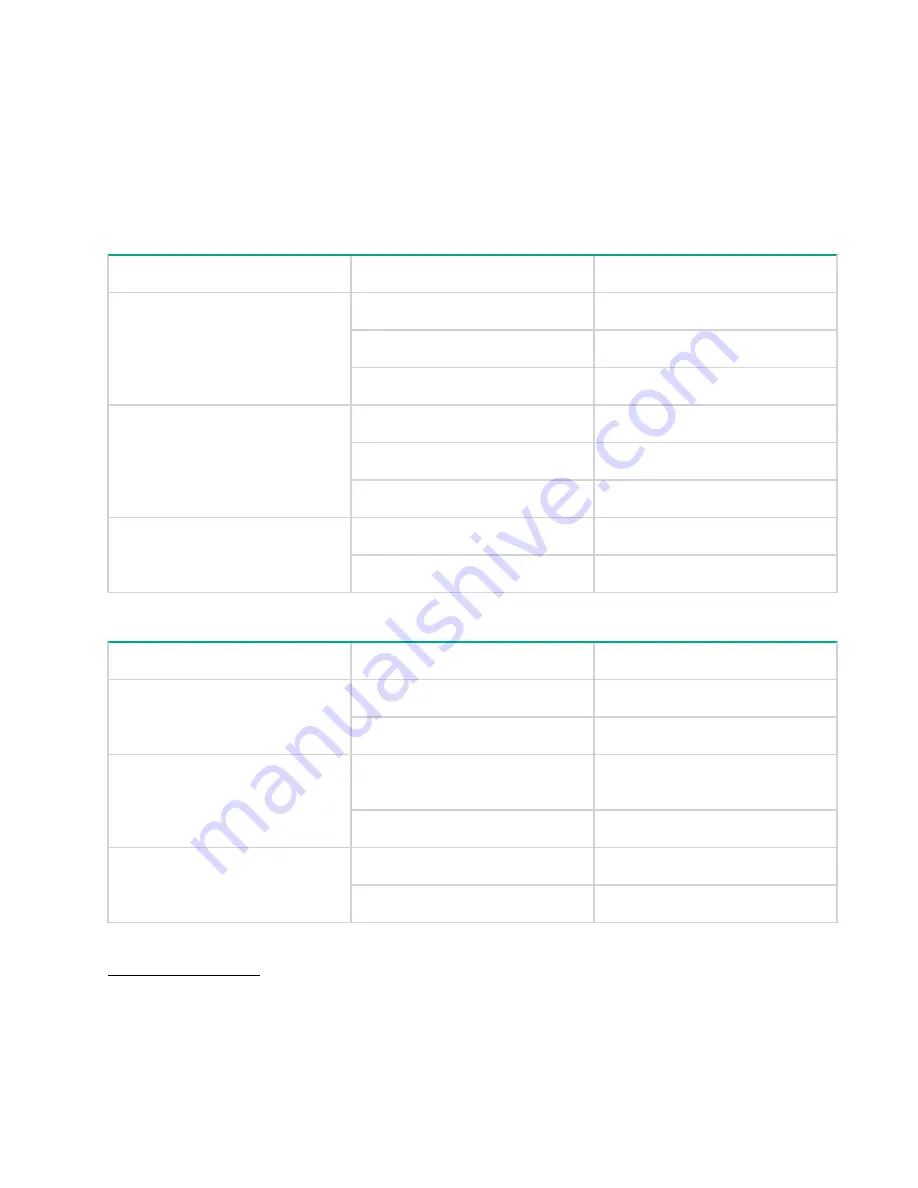
Table 11: Minimum disk drive configuration

Disk type

RAID level

Number of disk drives

LFF

SSD

RAID 10

4

RAID 5

6

RAID 6

12

10K SFF SAS

RAID 10

4

RAID 5

6

RAID 6

12

7.2K LFF MDL-SAS

RAID 10

4

RAID 6

12

Table 12: Supported drives in each tier

Tier

Drive type

Drive size

Tier 0

SFF SSD 12 Gb SAS

400 GB, 800 GB, 1.6 TB, 3.2 TB

LFF SSD 12 Gb SAS

400 GB, 800 GB

Tier 1

SFF 10K 12 Gb SAS

300 GB, 600 GB, 900 GB, 1.2 TB,
1.8 TB

SFF 15K 12 Gb SAS

300 GB, 600 GB

Tier 2

SFF 7200 12 Gb MDL-SAS

2 TB

LFF 7.2K 12 Gb MDL-SAS

2 TB, 4 TB, 6 TB, 8 TB

Related tasks
Installing a disk drive

 on page 53

24

 Adding storage system capacity

Содержание storevirtual 3200

Страница 1: ...uide Part Number 839939 003 Published March 2017 Edition 3 Abstract This guide provides instructions for configuring individual storage systems adding new disk drives or storage systems to existing configurations and using remote support ...

Страница 2: ...computer software Valid license from Hewlett Packard Enterprise required for possession use or copying Consistent with FAR 12 211 and 12 212 Commercial Computer Software Computer Software Documentation and Technical Data for Commercial Items are licensed to the U S Government under vendor s standard commercial license Links to third party websites take you outside the Hewlett Packard Enterprise we...

Страница 3: ...atus LEDs 19 Safely rebooting a storage controller 20 Adding storage system capacity 22 End to end process for adding drives and drive enclosures 22 Adding disk drives and drive enclosures 22 Verifying the state of the new drives and enclosures 22 Using the StoreVirtual Management Console to scale up the storage system 23 Verifying the added capacity in the StoreVirtual Management Console 23 Addin...

Страница 4: ...ifying the spare part number 42 Identifying swappable parts 42 Accessing component replacement videos 42 Parts only warranty service 42 Replaceable parts list 43 Warnings and precautions 50 Preventing electrostatic discharge 50 Equipment symbols 51 Required tools 51 Replacing a disk drive 52 Verifying disk drive failure 52 Removing a disk drive 52 Installing a disk drive 53 Verifying disk drive op...

Страница 5: ...ing the cache backup battery 73 Installing the cache backup battery 75 Verifying cache backup battery operation 77 Replacing the intercontroller link ICL 77 Before you begin 77 Removing the ICL 77 Installing the ICL 79 Verifying ICL operation 80 Migrating data from other StoreVirtual Storage systems 80 Remote support 81 Overview 81 Setting up customer information 81 Entering and modifying customer...

Страница 6: ...epair 92 Remote support 93 Warranty information 93 Regulatory information 93 Documentation feedback 94 Warranty and regulatory information 95 Warranty information 95 Regulatory information 95 Belarus Kazakhstan Russia marking 95 Turkey RoHS material content declaration 96 Ukraine RoHS material content declaration 96 6 Contents ...

Страница 7: ... options The QuickSpecs are available from the product page Terminology Following are definitions for the commonly used product terms Array enclosure A chassis with two storage controllers drives power supplies and fan modules Chassis A specialized casing designed to hold cover power cool and allow communication between two storage controllers or two I O modules drives two power supplies and fan m...

Страница 8: ...e bays or an SFF configuration with 25 drive bays There are four controller configurations available 3 4 1 2 Figure 1 HPE StoreVirtual 3200 Storage LFF front view 1 Disk drive locate UID 3 System status LED 2 Disk drive status LED 4 System locate UID push button 1 2 3 4 Figure 2 HPE StoreVirtual 3200 Storage SFF front view 1 Disk drive locate UID 3 System status LED 2 Disk drive status LED 4 Syste...

Страница 9: ...le 9 Power supply module 5 Controller module 1 2 3 4 5 6 7 8 9 10 Figure 4 HPE StoreVirtual 3200 Storage 1 GbE controller module 2 port 1 Controller locate UID 6 Service port Micro B USB 2 Controller status LED 7 Management port MGMT 3 Controller fault LED 8 1 GbE ports 4 USB type A port 9 Data port status LEDs 5 Recovery power button See Recovery Power button on page 12 10 SAS data port to option...

Страница 10: ...ional drive enclosure DP 1 6 Recovery power button See Recovery Power button on page 12 1 2 3 4 5 7 6 8 9 10 11 Figure 6 HPE StoreVirtual 3200 Storage 10 GbE controller module 2 port 1 Controller locate UID 7 Service port Micro B USB 2 Controller status LED 8 Management port MGMT 3 Controller fault LED 9 1 GbE ports 4 USB type A port 10 Data port status LEDs 5 10 GbE SFP ports 11 SAS data port to ...

Страница 11: ... enclosure DP 1 6 Recovery power button See Recovery Power button on page 12 2 3 4 5 1 7 6 8 9 10 11 Figure 8 HPE StoreVirtual 3200 Storage 8Gb 16 Gb Fibre Channel controller module 2 port 1 8 Gb 16 Gb Fibre Channel ports 7 Service port Micro B USB 2 Controller locate UID 8 Management port MGMT 3 Controller status LED 9 1 GbE ports 4 Controller fault LED 10 Data port status LEDs 5 USB type A port ...

Страница 12: ...ered on and causes a reboot of the controller HPE StoreVirtual 3000 drive enclosure The HPE StoreVirtual 3000 drive enclosure is available in either an LFF configuration with 12 drive bays or an SFF configuration with 25 drive bays The components on the rear of the drive enclosure are identical for both the LFF and SFF configurations 3 4 1 2 Figure 9 HPE StoreVirtual 3000 LFF front view 1 Disk dri...

Страница 13: ...upply 2 5 I O module locate UID 14 Fan Module 2 6 SAS data ports 15 Fan status LED 7 Data port status LEDs 16 Fan locate UID 8 Seven segment display 17 Fan Module 1 9 System locate UID push button Locating the product serial number on the hardware It may be necessary to provide the product serial number for support or service Procedure 1 Locate the serial number label on the rear of the enclosure ...

Страница 14: ...umber label Locating the product serial number in the Management Console Procedure 1 From the main menu select Storage System 2 Select Storage System Report The serial number is located in the Warranty Information section 14 Locating the product serial number in the Management Console ...

Страница 15: ...n interpreting the LED displays see Status LED descriptions on page 15 Powering off the storage system Currently there is not a way to power off the entire storage system controllers and drive enclosures from a software interface To power off a storage controller use the Recovery Power button on the rear of the controller See Recovery Power button on page 12 for more information To power off a dis...

Страница 16: ...hese indicators are also located on the rear panel directly above fan 2 Table 2 Power supply module status LED Indicator Display Description Status LED Green on Normal operation Green off Fault or no power Table 3 Fan module status LEDs Indicator Display Description Status LED Green on Normal operation Amber on Fault All LEDS off Fault or no power Locate UID Off Normal operation Blue on Location r...

Страница 17: ...lash Green on Manually initiated locate no I O no fault do not remove Flash Green flicker Manually initiated locate active I O no fault do not remove On Amber on Automatically initiated locate fault safe to remove Flash Amber on Automatically initiated locate fault do not remove Storage controller enclosure controller module status LEDs The following LEDs are used to verify array enclosure control...

Страница 18: ...tatuses table behave the same way for the following components Management ports Onboard 1 GbE LEDs 1 GbE LOM LEDs 10 GbE LOM LEDs Table 6 Ethernet LED statuses Green LED Amber LED Description Off Off Fault or no power Off On Link without activity Flash On Link with activity Fibre channel LED status Table 7 FC LED statuses Green LED Amber LED Description Off Off Fault or no power On Off Link at hig...

Страница 19: ...k at low speed no activity Flicker On Link at low speed with activity Flash Flash opposite of the green LED Location requested Data port SAS connected JBODs LED status Table 9 Data port SAS LED statuses Green LED Amber LED Description Off Off Fault or no power On Off Link at high speed no activity Flicker Off Link at high speed with activity Off On No link or no cable connected On On Link at low s...

Страница 20: ...requested I O module status LED Green on amber off Normal operation Green flashing amber off Shutdown in progress no fault Green off amber on Fault Green flashing amber on Shutdown in progress fault Green flashing amber flashing Shutdown in progress Locate UID Off Normal operation Blue on Location requested Safe to remove Blue flashing Location requested Do not remove Indicates that maintenance is...

Страница 21: ...trollers b On the navigation pane select the storage controller and then select Actions Power off or reboot on the content pane c Click Reboot d Enter the number of minutes for the system to wait before rebooting and then click OK e Review the warning message and then click Yes reboot f On the second confirmation message select the confirmation box and then click Yes reboot 3 Fail back the storage...

Страница 22: ...eVirtual storage system See Network cabling configurations for more information 7 Apply power to the new enclosure and wait one minute 8 Apply power to the StoreVirtual storage system Once the system is completely powered on log on to the StoreVirtual Management Console as described in the HPE StoreVirtual 3200 Storage Installation Guide Verifying the state of the new drives and enclosures Procedu...

Страница 23: ...om the Storage System menu on the content pane 4 Scroll down under the Drive Info section You can see all added drives with their respective drive models serial numbers capacity level and firmware revision details 5 Scroll down further to the Drive Status section Newly configured drives show a status of Active or Hot Spare depending upon the configuration chosen during the Add RAID operation 6 On ...

Страница 24: ... Minimum disk drive configuration Disk type RAID level Number of disk drives LFF SSD RAID 10 4 RAID 5 6 RAID 6 12 10K SFF SAS RAID 10 4 RAID 5 6 RAID 6 12 7 2K LFF MDL SAS RAID 10 4 RAID 6 12 Table 12 Supported drives in each tier Tier Drive type Drive size Tier 0 SFF SSD 12 Gb SAS 400 GB 800 GB 1 6 TB 3 2 TB LFF SSD 12 Gb SAS 400 GB 800 GB Tier 1 SFF 10K 12 Gb SAS 300 GB 600 GB 900 GB 1 2 TB 1 8 ...

Страница 25: ...e rear 2 NOTE It is easier to make this adjustment prior to mounting the rails 3 Position the left and right rack rails at the desired U position in the rack adjusting the rails to fit the rack as needed The front and rear bottom edges of the rails must align with the bottom of the EIA boundary in the lowermost U NOTE Rails are marked L and R with an arrow indicating the direction in which the rai...

Страница 26: ...ok snaps into place NOTE Make sure that the respective guide pins for the square or round hole rack align properly into the EIA column hole spacing 7 Secure the rear of the rack rail to the EIA column with either the round or square hole shoulder screws provided in the package 26 Adding storage system capacity ...

Страница 27: ...closure only after mounting the enclosure in the rack An enclosure with disk drives installed is too heavy to lift safely Procedure 1 Slide the enclosure into position on the rails 1 Secure the chassis into the rack by tightening the captive CTO screw 3 behind the latch on the front left and right bezel ears of the chassis 2 CAUTION The front CTO screw must be attached at all times when racked Ins...

Страница 28: ...lable storage capacity and provides additional redundancy and reliability Adding a new StoreVirtual 3200 storage system is limited to iSCSI configurations Adding a new storage system to an existing configuration Prerequisites The new storage system must be configured the same as the storage system in the existing management group and storage pool The new storage system must not be configured in a ...

Страница 29: ...ed when a storage system is not in a management group 6 On the StoreVirtual menu select Settings 7 Select General and then selectActions Add storage systems on the content pane Use Add IP address and Discover available systems as needed to discover storage systems on the network 8 Select a storage system to add to the management group and click OK 9 Use the StoreVirtual Management Console to selec...

Страница 30: ...sites Failover Manager support for automatic failover failback in a two site configuration without requiring a physical storage system in a third site Failover Manager for quorum management if the network connection between two sites becomes unavailable Failure protection through data replication site design and quorum managers A Multi Site SAN can protect against data center failures power or net...

Страница 31: ...ssigning application servers to the site where the server is located Application servers assigned to a site connect with iSCSI sessions only to storage systems in the same site when the storage in that site is available Use the Failover Manager Unless you have storage systems in three physical sites use a Failover Manager Put the Failover Manager on a third logical site On a network that is isolat...

Страница 32: ...edure Before beginning the Configuration Setup procedure ensure that you have completed the cabling for your system as described in the following sections Also ensure that you have the required IP addresses available The Configuration Setup procedure allows data and management traffic on the same subnet only Connecting the StoreVirtual 3200 Storage system to the network The array enclosure can be ...

Страница 33: ...ormance during the Configuration Setup procedure Physical connections Connect 1G 1 1G 2 1G 3 and 1G 4 on each controller to a switch eight 1 GbE connections Required IP addresses Two for the 1 GbE network on Controller 1 Two for the 1 GbE network on Controller 2 One for the VIP All other interfaces are disabled The following figure illustrates the cabling described Figure 15 Configuration using fo...

Страница 34: ... Physical requirements Connect 10G 1 and 10G 2 on each controller to a switch four 10 GbE connections The two 1 GbE ports must be disabled IP addresses required Two for the 10 GbE 10GBase T network on Controller 1 Two for the 10 GbE 10GBase T network on Controller 2 One for the VIP All other interfaces are disabled The following figure illustrates the cabling described 1 2 3 4 Figure 16 Configurat...

Страница 35: ...h controller to a switch four Fibre Channel connections Connect 1G 1 and 1G 2 on each controller to a switch four 1 GbE connections Required IP addresses One for the 1 GbE network on Controller 1 One for the 1 GbE network on Controller 2 One for the VIP Best Practice All other interfaces are disabled Figure 17 Configuration using four Fibre Channel ports and two switches on page 35 illustrates the...

Страница 36: ...es Connecting to one drive enclosure 1 2 Figure 18 One drive enclosure cabling configuration 1 Array enclosure 2 Drive enclosure 1 Connect DP 1 on the storage controller in slot 1 to DP 1 on the I O module in slot 1 of the drive enclosure 2 Connect DP 1 on the storage controller in slot 2 to DP 1 on the I O module in slot 2 of the drive enclosure Connecting to two drive enclosures 1 2 3 Figure 19 ...

Страница 37: ...odule in slot 1 of the first drive enclosure 2 Connect DP 2 on the I O module in slot 1 of the first drive enclosure to DP 1 on the I O module in slot 1 of the second drive enclosure 3 Connect DP 2 on the I O module in slot 1 of the second drive enclosure to DP 1 on the I O module in slot 1 of the third drive enclosure 4 Connect DP 1 on the storage controller in slot 2 to DP 1 on the I O module in...

Страница 38: ...the process Bond type For each controller static IP addresses that are available on the network two for iSCSI one for Fibre Channel per bond Subnet mask Bond types The following types of bonding are supported with the HPE StoreVirtual 3200 Storage System ALB default Can only be created between two or four interfaces that have the same speed No additional network switch configuration is required Th...

Страница 39: ...orts All four 1G ports are bonded and share one subnet mask Controller with a 10GbE card 1 Option card 10GbE ports 2 Built in 1G ports The 10GbE ports are bonded and share a subnet mask The built in 1G ports are in a different bond The 10GbE and built in 1G ports must be on different subnets but they can be used simultaneously Managing the network 39 ...

Страница 40: ... iSCSI configurations The system can use either a OS level multipathing driver or a driver provided by a vendor such as a Windows multipath driver DSM or a VMware multipath driver MEM The iSCSI configuration uses MLTP which provides multiple LUNs on a single target iSCSI multipathing with DSM or MEM Access the SVMC to configure StoreVirtual networking See the StoreVirtual Management Console Online...

Страница 41: ...etworking See the StoreVirtual Management Console Online Help for more information Each controller has a pair of physical network interfaces that are bonded together Two IP addresses are assigned to the bond for optimal performance A total of four or eight IP addresses can be defined depending upon the number of ports A virtual IP address can be configured The client must be enabled with multipath...

Страница 42: ... replacement Warm swappable parts are identified by gray colored touch points The system will not fail if the part is removed but data loss may occur if the replacement procedure is not followed correctly Cold swappable parts are identified by blue touch points The system must be powered off or otherwise suspended before replacing the part Accessing component replacement videos Hewlett Packard Ent...

Страница 43: ...er enclosure replaceable parts Table 13 Storage controller enclosure parts list Callout Description Spare part name Spare part number CSR type 1 1 Chassis Bezel Ear N A N A N A 2 2 Chassis Bezel Ear N A N A N A 2 3 Drive Cage SPS Cage SFF Hard Disk Drive HDD 781530 001 N A 2 SPS Cage LFF Hard Disk Drive HDD 781531 001 N A 2 4 Backplane PCA SFF HDD Backplane 832029 001 Mandatory PCA LFF HDD Backpla...

Страница 44: ... FC 840216 001 Mandatory SPS Controller Node Assy SFF 1GbE 4P 840217 001 Mandatory SPS Controller Node Assy LFF 1GbE 4P 840218 001 Mandatory SPS Controller Node Assembly SFF 10GbE 840219 001 Mandatory SPS Controller Node Assembly LFF 10GbE 840220 001 Mandatory 10 Fan module SPS Fan Assembly 781532 001 Mandatory 11 UID health module3 SPS UID Health Module 740127 001 Mandatory 12 Battery SPS BATT PA...

Страница 45: ...SAS 10K SFF HDD 832972 001 Mandatory HPE SV3000 1 8TB 12G SAS 10K SFF HDD 832973 001 Mandatory HPE SV3000 2TB 12G SAS 7 2K SFF MDL HDD 832978 001 Mandatory HPE SV3000 2TB 12G SAS 7 2K LFF MDL HDD 832980 001 Mandatory HPE SV3000 4TB 12G SAS 7 2K LFF MDL HDD 832976 001 Mandatory HPE SV3000 6TB 12G SAS 7 2K LFF MDL HDD 832977 001 Mandatory HPE SV3000 8TB 12G SAS 7 2K LFF MDL HDD 832981 001 Mandatory ...

Страница 46: ...ndatory 15 Fan control card cable assembly SPS Fan interconnect cable 740127 001 Mandatory 16 Drive blank not shown SPS BLANK LFF HDD SPS HDD BLANK SFF Gen8 667279 001 670033 001 Mandatory 17 Rail kit not shown SPS RAIL KIT 2U 700520 001 Mandatory 18 CA EXT iPASS x4 HD to HD 3 0 0 5 not shown CA EXT iPASS x4 HD to HD 3 0 0 5 717432 001 Mandatory 19 Transceiver not shown 16Gb FC SFP 793444 001 Mand...

Страница 47: ...rn to depot repair is not provided under warranty 2 Not a replaceable spare part 3 The UID Health Module Rear Unit ID Fan Control Card cable assembly and intercontroller link are shipped as a single spare replacement 1 2 3 4 5 6 7 8 9 10 11 13 12 Figure 24 Drive enclosure replaceable parts Table 14 Drive enclosure parts list Callout Description Spare part name Spare part number CSR type 1 1 Chassi...

Страница 48: ...ule SPS I O Module SFF 2 Port 781533 001 Mandatory SPS I O Module LFF 2 Port 781867 001 Mandatory 10 Fan module SPS Fan Assembly 781532 001 Mandatory 11 UID health module SPS UID Health Module 740127 001 Mandatory 12 Fan control card cable assembly SPS Fan interconnect cable 740127 001 Mandatory 13 Disk drive HPE SV3000 8TB 12G SAS 7 2K LFF MDL HDD 832981 001 Mandatory HPE SV3000 300GB 12G SAS 15K...

Страница 49: ...S 7 2K SFF MDL HDD 832978 001 Mandatory HPE SV3000 2TB 12G SAS 7 2K LFF MDL HDD 832980 001 Mandatory HPE SV3000 4TB 12G SAS 7 2K LFF MDL HDD 832976 001 Mandatory HPE SV3000 6TB 12G SAS 7 2K LFF MDL HDD 832977 001 Mandatory HPE SV3000 400GB 12G SAS 2 5in MU SSD 834291 001 Mandatory HPE SV3000 800GB 12G SAS 2 5in MU SSD 834292 001 Mandatory HPE SV3000 1 6TB 12G SAS 2 5in MU SSD 834293 001 Mandatory ...

Страница 50: ...ic sensitive devices or micro circuitry Proper packaging and grounding techniques are necessary precautions to prevent damage To prevent electrostatic damage observe the following precautions Transport products in static safe containers such as conductive tubes bags or boxes Keep electrostatic sensitive parts in their containers until they arrive at static free workstations Cover workstations with...

Страница 51: ...njury from electric shock remove all power cords to completely disconnect power from the system Any product or assembly marked with these symbols indicates that the component exceeds the recommended weight for one individual to handle safely To reduce the risk of personal injury or damage to the equipment Remove all hot pluggable power supplies and modules to reduce the overall weight of the devic...

Страница 52: ...s see the Disk drive status LEDs table 2 Check the disk drive status from the StoreVirtual 3200 Management Console Navigate to the Disks section of the StoreVirtual Management Console The Health tile on the Disks Overview window displays the disk status NOTE From the StoreVirtual Management Console select Locate to turn on the disk UUID blue LED and ensure that you are replacing the correct disk d...

Страница 53: ...losure bay 2 Figure 27 LFF disk drive removal Figure 28 SFF disk drive removal Installing a disk drive CAUTION To prevent improper cooling and thermal damage operate the enclosure only when either a disk drive or a drive blank is installed in every bay Procedure 1 Remove the drive blank Installing a disk drive 53 ...

Страница 54: ...ton on the disk drive NOTE Both LFF and SFF disk drives shown Figure 30 LFF handle release button Figure 31 SFF handle release button 3 Swing out the latch handle on the drive Then slide the drive into the bay 1 pressing firmly on the drive to seat it Close the latch handle 2 pressing firmly until it locks into place 54 Removing and replacing hardware components ...

Страница 55: ...nt Console select Configure RAID to add the new storage See the HPE StoreVirtual Online Help for more information Verifying disk drive operation IMPORTANT When a disk drive is inserted in an operational enclosure the drive LEDs flash to indicate that the drive is seated properly and receiving power Check the disk drive status LEDs to ensure that the drive is operating properly For more information...

Страница 56: ...s to ensure it has failed For the location of the controller module LEDs see Storage controller enclosure on page 8 For information on interpreting the status see Related reference Verify the controller module status from the StoreVirtual Management Console Navigate to the Storage Controllers section The controller status is listed next to the controller name in the left list pane Related referenc...

Страница 57: ... controller Batteries are not supplied with a replacement controller 1 Slide the replacement controller module 1 into the enclosure and close the controller module handle 2 2 Retighten the captive retainer thumbscrew 3 3 2 1 3 Reconnect all cables to the controller module 4 To verify that the controller module is operating properly check the status LEDs For more information see Related reference I...

Страница 58: ...le Online Help for more information Replacing a drive enclosure I O module Verify I O module failure Before replacing an I O module verify its status using one of the following methods Ensure that the I O module has failed by verifying the I O module status LEDs For the location of the I O module LEDs see HPE StoreVirtual 3000 drive enclosure on page 12 For information on interpreting the status s...

Страница 59: ... I O module handle 2 2 Tighten the captive retainer thumbscrew 3 3 2 1 3 Reconnect all cables to the I O module Verifying I O module operation Procedure 1 Ensure the I O module is operating properly by checking the status LEDS For more information see Related reference Related reference Storage controller enclosure controller module status LEDs on page 17 Installing an I O module 59 ...

Страница 60: ...of the power supply LEDs see HPE StoreVirtual 3000 drive enclosure on page 12 For information on interpreting the status see Related reference Related reference Status LED descriptions on page 15 Removing a power supply Procedure 1 Remove the power cable from the power supply to be replaced 2 Press the latch 1 and slide the power supply module out of the enclosure 2 60 Replacing a power supply mod...

Страница 61: ... Before you begin IMPORTANT Make sure that you have the replacement fan module unpacked and available for installation before removing the failed fan Ensure proper cooling because the fan module replacement must be done within three minutes or the temperature rises Verifying fan module failure Before replacing a fan module verify its status using one of the following methods Procedure 1 Ensure tha...

Страница 62: ...ns 1 1 1 2 2 Slide the module 2 out of the enclosure Installing a fan module Procedure 1 Slide the replacement fan module into the enclosure until it clicks into place Verifying fan module operation Procedure 1 Ensure that the fan module is operating properly by checking the status LEDs For more information see Related reference Related reference Status LED descriptions on page 15 Replacing the UI...

Страница 63: ...emoving the UID health module Procedure 1 Power off the enclosure 2 Disconnect all cables from the enclosure including the power cables 3 Remove fan module 2 See Removing a fan module on page 62 4 Loosen the rear CTO hold down bracket 5 Loosen the captive CTO screws 2 behind the latch 1 on the front left and right bezel ears of the enclosure 6 Slide the enclosure out of the rack and set it on a se...

Страница 64: ...8 Disconnect the UID health module cable from the backplane 9 Remove the UID health module retaining screw 1 64 Removing and replacing hardware components ...

Страница 65: ...enclosure cover and press the hood latch down to engage the latch 6 Install the enclosure in the rack 7 Tighten the front retaining screws 8 Install fan module 2 See Installing a fan module on page 62 9 Reconnect all cables to the enclosure including the power cables Verifying UID health module operation Procedure 1 When the enclosure has completed its power on sequence check all enclosure status ...

Страница 66: ...t number before removing them to ensure they are reinstalled in the proper enclosure bays 6 Remove all the disk drives See Removing a disk drive on page 52 7 Remove the power supplies See Removing a power supply on page 60 8 Perform one of the following depending on which type of enclosure is involved a If you are replacing the backplane in a drive enclosure remove the I O modules See Removing an ...

Страница 67: ...4 5 6 7 Number Cable 1 Front UID health module 2 Fan 3 Fan 4 Rear UID health module 5 Power distribution unit 6 Power supply 7 Power supply 12 Remove the eight drive cage retaining screws There are four to each side Removing and replacing hardware components 67 ...

Страница 68: ...ottom of the enclosure are all correctly located in the drive cage NOTE Depending on the specific unit there are six or eight locating pins 4 Install the eight drive cage retaining screws 5 Connect the two UID health module cables 6 Connect the power cables 7 Connect the fan cables 8 Reconnect the power distribution unit 9 Install the enclosure cover and press the hood latch down to engage the lat...

Страница 69: ...ed its power on sequence check all enclosure status LEDs to ensure the enclosure is operating properly For more information see Status LED descriptions on page 15 Replacing a Fibre Channel SFP The SFP is on the rear of the array enclosure and serves as the storage controller FC port WARNING When the system is on do not stare at the fibers Doing so could damage your eyes Removing a Fibre Channel SF...

Страница 70: ... card cable assembly Procedure 1 Power off the array enclosure 2 Disconnect all cables from the enclosure including the power cables 3 Loosen the captive CTO screws 2 behind the latch 1 on the front left and right bezel ears of the enclosure 4 Slide the enclosure out of the rack and set it on a secure surface 5 Remove the rear CTO hold down bracket 6 Remove the storage controller enclosure from th...

Страница 71: ...move fan control card cable from the backplane 3 Remove the T 15 screw 4 Slide the fan control card bracket sideways to free it from the retaining pins and lift it out 5 Remove the fan cable from the bracket 1 2 3 6 Push the connector release in 7 Slide the connector to keyed slots and push out Removing the fan control card cable assembly 71 ...

Страница 72: ... the retaining pins 5 Reinstall the captive T 15 screw 6 Attach the fan control card cable to the backplane 7 Replace the enclosure cover and press the hood latch down to latch 8 Replace the fan modules See Replacing a fan module on page 61 9 Replace the enclosure in the rack 10 Install the captive CTO screws 11 Tighten the front retaining screws 12 Replace the I O module cables 13 Replace the pow...

Страница 73: ...ses See Ethernet LED statuses on page 18 for LED status information Replacing the cache backup battery Verifying cache backup battery failure Procedure 1 The system monitors battery operation and logs any faults Use the StoreVirtual Management Console to view the battery status Removing the cache backup battery Procedure 1 Remove the controller module from the array enclosure For more information ...

Страница 74: ...w the DIMM or battery to dangle by the cable 4 Remove the battery from the controller module Press the mounting tray tab on the side wall to release the catch lock 5 Remove the battery from the mounting tray 74 Removing and replacing hardware components ...

Страница 75: ...attery Procedure 1 Install the replacement battery in the mounting tray 2 Install the battery and mounting tray in the controller module Ensure the tab snaps into place to secure the mounting tray Installing the cache backup battery 75 ...

Страница 76: ...Connect the replacement battery cable to the DIMM 4 Install the DIMM in the controller module by inserting the DIMM in the socket 1 and engaging the levers 2 76 Removing and replacing hardware components ...

Страница 77: ...be performed only if Hewlett Packard Enterprise Support has determined that the ICL has failed and must be replaced CAUTION This procedure requires removing the enclosure from the rack Before removing the enclosure ensure that data on the system is backed up Back up data if necessary Removing the ICL Procedure 1 Power off the array enclosure 2 Disconnect all cables from the enclosure including the...

Страница 78: ...losure from the rack 7 Pull the hood latch up and back 1 and 2 and lift the enclosure cover up and remove it 3 8 Remove both controller modules See Removing a controller module on page 56 9 Remove the three ICL bracket mounting screws 1 and remove the bracket 78 Removing and replacing hardware components ...

Страница 79: ...he ICL bracket using the three bracket mounting screws 3 Install both controller modules See Installing a controller module on page 57 4 Install the enclosure cover and press the hood latch down to engage the latch 5 Install the enclosure in the rack 6 Tighten the front retaining screws CAUTION The front CTO retaining screws must be attached at all times when the enclosure is racked 7 Reconnect al...

Страница 80: ...tions on page 15 Migrating data from other StoreVirtual Storage systems The StoreVirtual Migration Manager enables you to migrate data from a P4000 G2 StoreVirtual 4000 or StoreVirtual VSA system to a StoreVirtual 3200 system For more information see the StoreVirtual Migration Manager documentation which includes a user guide and installation instructions at http www hpe com info sv3200 docs 80 Ve...

Страница 81: ...data to Hewlett Packard Enterprise Support using an HTTPS connection over the Internet If needed you can specify a web proxy server to connect to the Internet Alerts are transmitted over the firewall friendly port 443 NOTE Hewlett Packard Enterprise recommends entering the entitlement serial and product numbers even if you do not intend to use Remote Support The numbers are saved with the configur...

Страница 82: ...ote Support monitors your system and allows the system to proactively contact Hewlett Packard Enterprise if issues arise Hewlett Packard Enterprise Remote Support page The Remote Support page allows you to view the level of remote support 82 Remote Support settings ...

Страница 83: ...Support If you select No Hewlett Packard Enterprise and partners will not contact you based on the data sent back from Remote Support If Remote Support is disabled then HPE support will not contact you based on automated cases Target HPE server The HPE server that receives the event messages The server is automatically populated and must not be changed unless you have a specific reason to do so Su...

Страница 84: ...emote Support Settings page on page 84 Figure 35 Remote Support Settings page Proxy settings The Proxy Settings page displays information about the proxy settings if required to connect to the target HPE server Procedure 1 From the StoreVirtual main menu select Settings 2 Click Edit on the Proxy Settings page 3 Enter or edit the appropriate information 4 Click OK 84 Configuring and modifying Remot...

Страница 85: ...nternet Protocol Protocol used by the proxy server Proxy server Proxy server IP address Port Port used by the proxy server Authentication required If authentication is required to access the proxy server the Login ID Password and Confirm password fields are required Clear this field if authorization is not required to access the proxy and Login ID User name required to access the proxy server Tabl...

Страница 86: ...s could contact you to suggest optimizations Entitlement information could not be acquired from the system EID_RSVS_CONN_STATUS_ERROR There are connectivity issues such as Proxy server or Hewlett Packard Enterprise URL is not reachable DNS is not configured properly EID_RSVS_SUMM_STATUS_MAINTENANCE Device is under maintenance EID_RSVS_REG_STATUS_NOT_REGISTERED Device is not registered EID_RSVS_SUM...

Страница 87: ...t HPE server field on the Remote Support Settings page can only be changed when Support mode is on To enable support mode Procedure 1 From the StoreVirtual main menu select Support 2 Click Edit on the Support Mode page 3 Select Support mode and change the selection to On 4 Click OK Figure 37 Support Mode page Support mode 87 ...

Страница 88: ...Installing a 3PAR StoreServ disk enclosure into a StoreVirtual 3200 Storage system results in the enclosure status reporting unknown in the SVMC and via REST Cause A 3PAR StoreServ enclosure is not compatible with the StoreVirtual array and should not be used Action Procedure 1 Shut down the storage system and remove the 3PAR StoreServ disk enclosure An iSCSI volume that becomes unavailable for ap...

Страница 89: ...rd Value window opens 4 Enter a value of 120 5 Click OK 6 Save your changes and exit the Registry 7 Reboot the system RAID array remains degraded after hot spares rebuild Symptom After a disk drive fails and the disk drive designated as the hot spare is rebuilt RAID remains in a degraded state Cause The RAID configuration remains degraded until the failed drives are replaced and the new drives reb...

Страница 90: ...Action Procedure 1 You can ignore the information the system will work as designed The issue corrects itself once the failed controller is replaced 90 Troubleshooting ...

Страница 91: ...ibrary www hpe com info EIL Single Point of Connectivity Knowledge SPOCK Storage compatibility matrix www hpe com storage spock Storage white papers and analyst reports www hpe com storage whitepapers For additional websites see Support and other resources Websites 91 ...

Страница 92: ...pe com support hpesc Hewlett Packard Enterprise Support Center Software downloads www hpe com support downloads Software Depot www hpe com support softwaredepot To subscribe to eNewsletters and alerts www hpe com support e updates To view and update your entitlements and to link your contracts and warranties with your profile go to the Hewlett Packard Enterprise Support Center More Information on ...

Страница 93: ...tral Proactive Care service activation www hpe com services proactivecarecentralgetstarted Warranty information To view the warranty for your product see the Safety and Compliance Information for Server Storage Power Networking and Rack Products document available at the Hewlett Packard Enterprise Support Center www hpe com support Safety Compliance EnterpriseProducts Additional warranty informati...

Страница 94: ...cumentation feedback Hewlett Packard Enterprise is committed to providing documentation that meets your needs To help us improve the documentation send any errors suggestions or comments to Documentation Feedback docsfeedback hpe com When submitting your feedback include the document title part number edition and publication date located on the front cover of the document For online help content i...

Страница 95: ...ties HPE Enterprise Servers www hpe com support EnterpriseServers Warranties HPE Storage Products www hpe com support Storage Warranties HPE Networking Products www hpe com support Networking Warranties Regulatory information Belarus Kazakhstan Russia marking Manufacturer and Local Representative Information Manufacturer information Hewlett Packard Enterprise Company 3000 Hanover Street Palo Alto ...

Страница 96: ...w decade with 2000 as the starting point for example 238 2 for 2002 and 38 for the week of September 9 In addition 2010 is indicated by 0 2011 by 1 2012 by 2 2013 by 3 and so forth YYWW where YY indicates the year using a base year of 2000 for example 0238 02 for 2002 and 38 for the week of September 9 Turkey RoHS material content declaration Ukraine RoHS material content declaration 96 Turkey RoH...

Отзывы: