background image

Operating the SDLT Drive

24

SDLT Tape Drives Reference Guide

Write-Protecting a Cartridge

The cartridge has a write-protect switch to prevent accidental erasure of data. 
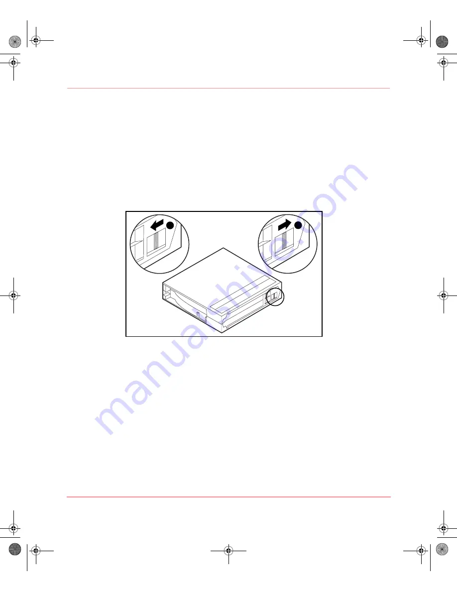
Before loading the cartridge into the drive, position the write-protect switch on the 
front of the cartridge. Figure 3-4 illustrates using the write-protect switch. By 
moving the switch to the left 

1

, the cartridge is write-protected, and by moving 

the switch to the right 

2

, the cartridge is write-enabled.

Moving the cartridge write-protect switch to the left while the cartridge is in the 
SDLT drive, illuminates the red indicator immediately. If the drive is writing to the 
cartridge, write-protect does not begin until the current write command completes.

Figure 5:  Cartridge with right-protect switch

2

1

201412-003.book  Page 24  Thursday, October 3, 2002  9:05 AM

Содержание StorageWorks SDLT 320

Страница 1: ...es Third Edition October 2002 Part Number 201412 003 This guide is to be used as step by step instructions for installation and as a reference for operation troubleshooting and future upgrades 201412 003 book Page i Thursday October 3 2002 9 05 AM ...

Страница 2: ...poration is a wholly owned subsidiary of Hewlett Packard Company Microsoft MS DOS Windows and Windows NT are trademarks of Microsoft Corporation in the U S and or other countries The Open Group OSF 1 UNIX are trademarks of The Open Group in the U S and or other countries All other product names mentioned herein may be trademarks of their respective companies Hewlett Packard Company shall not be li...

Страница 3: ...eller xii 1 Introduction Overview 2 HP StorageWorks Native Driver CD 2 System Requirements 3 Data Compression 4 2 Operating System Device Drivers Device Drivers 5 Installing Drivers on Windows NT 4 0 6 Installing Drivers on Windows 2000 7 Novell NetWare 8 ASPI Support 8 HP Tru64 UNIX 9 DDR Recognition 9 Turning Compression On 10 Example 1 10 Example 2 10 Turning Compression Off 10 Open VMS 11 2014...

Страница 4: ...Write Protecting a Cartridge 24 Cartridge Handling and Storage 25 DRTape Solution 27 System Requirements 28 Using the Disaster Recovery Solution 28 Creating a Disaster Recovery Tape 29 Restoring a System 29 4 Troubleshooting the SDLT Drive What to do if there is a Problem 31 Library and Tape Tools 33 A Regulatory Compliance Notices Federal Communications Commission Notice 35 Class A Equipment 35 C...

Страница 5: ...5 D Manually Removing a Cartridge Tools 47 Preparing the SDLT Drive 48 Disassembling the SDLT Drive 48 Removing the Bezel 49 Removing the Cover 50 Rewinding the Tape into the Cartridge 51 Removing the Left Guide 52 Disconnecting the Leader Pin from Cartridge Buckle 53 Removing the Cartridge 54 Assembling the SDLT Drive 54 E Density Select Specifying a Device 55 Selecting a Density 56 Using Media P...

Страница 6: ...Contents vi SDLT Tape Drives Reference Guide 201412 003 book Page vi Thursday October 3 2002 9 05 AM ...

Страница 7: ...ference guide provides information to help you Install the operating system device drivers Operate the SDLT drive Troubleshoot the SDLT drive About this Guide topics include Conventions page viii Rack Stability page xi Getting Help page xi 201412 003 book Page vii Thursday October 3 2002 9 05 AM ...

Страница 8: ...vention Cross reference links Figure 1 Key and field names menu items buttons and dialog box titles Bold File names application names and text emphasis Italics User input command and directory names and system responses output and messages Monospace font COMMAND NAMES are uppercase monospace font unless they are case sensitive Variables monospace italic font Website addresses Underlined sans serif...

Страница 9: ...formation Equipment Symbols The following equipment symbols may be found on hardware for which this guide pertains They have the following meanings Any enclosed surface or area of the equipment marked with these symbols indicates the presence of electrical shock hazards Enclosed area contains no operator serviceable parts WARNING To reduce the risk of injury from electrical shock hazards do not op...

Страница 10: ...ndicate the presence of multiple sources of power WARNING To reduce the risk of injury from electrical shock remove all power cords to completely disconnect power from the power supplies and systems Any product or assembly marked with these symbols indicates that the component exceeds the recommended weight for one individual to handle safely WARNING To reduce the risk of personal injury or damage...

Страница 11: ...ing this guide contact an HP authorized service provider or access our website http www hp com HP Technical Support In North America call technical support at 1 800 652 6672 available 24 hours a day 7 days a week Note For continuous quality improvement calls may be recorded or monitored Outside North America call technical support at the nearest location Telephone numbers for worldwide technical s...

Страница 12: ... hp com country us eng prodserv storage html From this website select the appropriate product or solution HP Authorized Reseller For the name of your nearest HP authorized reseller In the United States call 1 800 345 1518 In Canada call 1 800 263 5868 Elsewhere see the HP website for locations and telephone numbers http www hp com 201412 003 book Page xii Thursday October 3 2002 9 05 AM ...

Страница 13: ...T Tape Drives Reference Guide 1 Introduction This chapter covers the following topics Overview HP Native Driver CD System requirements Data compression 201412 003 book Page 1 Thursday October 3 2002 9 05 AM ...

Страница 14: ...ximize the amount of data that can be stored on a tape The SDLT uses a clustered magnetic resistive MR head technology to improve data density uses Partial Response Maximum Likelihood PRML technology to provide increased performance and has a robust tape buckling system for reliability Figure 1 HP SDLT drive HP StorageWorks Native Driver CD The HP StorageWorks Native Driver CD included in the SDLT...

Страница 15: ...ries of controllers that support the SDLT drive and which ones are recommended For a list of specific controllers and adapters that support the SDLT drive refer to http www hp com country us eng prodserv storage html Table 2 Supported Controllers Controller Categories Recommended Fast SCSI 2 Narrow No Fast SCSI 2 Wide No Wide Ultra SCSI Yes Ultra 2 SCSI Yes Ultra 3 SCSI Yes Note Equipping the serv...

Страница 16: ...and a compressed data transfer rate of 22 MB s The SDLT 320 has a compressed capacity of 320 GB and a compressed data transfer rate of 32 MB s The SDLT drive ships from the factory with data compression enabled for writing In this mode data is always compressed when writing to the tape but the drive is capable of reading both compressed and native tapes For the drive to write native data the data ...

Страница 17: ...penVMS Red Hat Linux SuSe Linux Caldera UnixWare Caldera Open UNIX Caldera OpenServer Caldera Open Linux For an updated list of supported operating systems refer to www compaq com support files Click on Tape Storage under the heading Storage Device Drivers Device drivers for Intel based systems are located on the HP StorageWorks Native Driver CD 201412 003 book Page 5 Thursday October 3 2002 9 05 ...

Страница 18: ...ces dialog box is displayed and indicates that the driver for the new tape drive is not loaded If the system does not automatically scan for new devices select Detect This scanning process creates a list of device drivers available for installation 4 In the Install Driver dialog box click Have Disk The Install From Disk dialog box is displayed 5 In the Copy manufacturer s files from field type the...

Страница 19: ... category under the icon After the correct driver is installed the device will be correctly displayed in the tape drives category To install the SDLT tape driver select the tape drive under device manager and do the following 1 Right click the drive and select Properties 2 Select the Driver tab 3 Click Update Driver to launch the Update Device Driver Wizard 4 When prompted select the option to dis...

Страница 20: ...provided by Computer Associates or Veritas BackupExec refer to the information provided with the application NLM to determine whether it uses ASPI The ASPI drivers Cpqsaspi nlm Device Driver Functional Specification DDFS and Nwaspi nlm NetWare Peripheral Architecture NWPA provide ASPI support for the SCSI architecture for applications that require this interface Note Some ISPs such as Veritas use ...

Страница 21: ...can be effectively doubled when the tape drive has been instructed to turn on compression This is known as hardware compression Hardware compression is controlled by the drive firmware and should be used instead of the software compression that is sometimes provided by software products Check the software application manual to understand the interaction of the application with regard to hardware c...

Страница 22: ...l turn hardware compression off see the SDLT drive description in the ddr dbase file online 1 3 5 or 7 will turn hardware compression on Example 2 Another example to turn on compression using a tar command is tar cvf dev tape tape5c filename txt Where tape5 the tape device as known by the system shown in the file command in this case tape unit 5 c compression on Turning Compression Off The followi...

Страница 23: ...ve has been instructed to turn on compaction This is known as hardware compaction and should be used instead of the software compaction that is sometimes provided by software products The SDLT drive is instructed by the user to turn on hardware compaction through use of the OpenVMS INITIALIZE and MOUNT commands See these two commands using Open VMS help from the prompt The format for the INITIALIZ...

Страница 24: ... assigns the logical name BOOKS to the tape Example 2 INIT MEDIA_FORMAT NOCOMPACTION MKA400 BOOKS MOUNT MEDIA_FORMAT COMPACTION MKA400 BOOKS This MOUNT command attempts a Files 11 mount of a tape labeled BOOKS with data compaction and record blocking enabled Because the tape was initialized with compaction disabled the MOUNT qualifier MEDIA_FORMAT COMPACTION has no effect 201412 003 book Page 12 T...

Страница 25: ...quired The operating system defaults to a generic SCSI device and to the default settings of the tape drive The SDLT drive provides compression so that the storage capability for tapes can be effectively doubled when the SDLT drive has been instructed to turn on compaction This is known as hardware compaction and should be used instead of the software compaction that is sometimes provided by softw...

Страница 26: ...tings of the tape drive The SDLT drive provides compression so that the storage capability for tapes can be effectively doubled when the SDLT drive has been instructed to turn on compaction This is known as hardware compaction and should be used instead of the software compaction that is sometimes provided by software products Table 6 Additional tapecntl Commands Task Command Retention Tape tapecn...

Страница 27: ...n 1 Tape Decompression 1 Note Tape Decompression will always be set to 1 Table 7 Additional tapecntl Command Task Command Retention Tape tapecntl t dev rmt ctape1 Rewind Tape tapecntl w dev rmt ctape1 Tar Write tar cvf dev rmt ctape1 largefile Tar Read tar xvf dev rmt ctape1 DD Write dd if largefile of dev rmt ctape1 bs 51 DD Read dd if dev rmt ctape1 of largefile bs 512 201412 003 book Page 15 Th...

Страница 28: ...e xstatus tape xstatus dev xStp0 Tape Retention tape reten dev xStp0 Tape Erase tape erase dev xStp0 Tape Reset tape reset dev xStp0 Tape Rewind tape rewind dev xStp0 Tape Block Size tape getblk dev xStp0 Tape Write File Mark tape wfm dev xStp0 Tape Get Compression tape getcomp dev xStp0 Tar Write tar cvf dev rStp0 largefile Tar Read tar xvf dev rStp0 Cpio Write cpio ocBmud O dev rStp0 Cpio Read c...

Страница 29: ... Tape mt f dev st0 rewind Set Tape to End Of Data mt f dev nst0 eod Set Tape Block Size mt f dev st0 setblk 1024 Set Compression to disabled mt f dev st0 compression 0 Verify Compression mt f dev st0 datcompression Set Compression to Enabled mt f dev st0 compression 1 Get Compression mt f dev st0 datcompression Tape Load mt f dev st0 load Tape Unload mt f dev st0 offline Table 10 Additional Comman...

Страница 30: ...Operating System Device Drivers 18 SDLT Tape Drives Reference Guide 201412 003 book Page 18 Thursday October 3 2002 9 05 AM ...

Страница 31: ... storage DRTape Solution Power On Self Test When power is initially applied the SDLT drive performs a Power On Self Test POST After the user powers up the drive the green indicator flashes while POST is performing When the green indicator is illuminated the drive is ready for operation Note If the amber indicator is illuminated a problem has been detected See Chapter 4 Troubleshooting the SDLT Dri...

Страница 32: ... Cartridge Types and Formats SDLT 220 SDLT 320 Media Compatibility SDLT Tape 1 DLT Tape IV Read only DLT Tape I TRS13 Model Read Only SDLT Tape 1 DLT Tape IV Read only DLT Tape I Read Only Table 12 Media Kit Part Numbers Media Kit Part Number SDLT 20 Pack 188527 B26 SDLT 10 Pack 188527 B22 SDLT 5 Pack 188527 B21 201412 003 book Page 20 Thursday October 3 2002 9 05 AM ...

Страница 33: ...lization process begins and the green indicator flashes When the cartridge is at the beginning of tape BOT marker the green indicator is illuminated The cartridge is now ready for use Caution If reusing a prerecorded cartridge and writing from BOT all prerecorded data is lost Unloading a Cartridge To unload a cartridge press the Eject button or issue an eject command in the software application 20...

Страница 34: ... Tape Drives Reference Guide Front Panel Indicators and Buttons Figure 3 Identifying the SDLT 220 front panel indicators Figure 4 Identifying the SDLT 320 front panel indicators 201412 003 book Page 22 Thursday October 3 2002 9 05 AM ...

Страница 35: ...ator Icon Color Action Explanation SDLT 220 Red ON Cartridge is write protected SDLT 320 Red ON SDLT 110 format data tape Red Blinking Density change is pending Green Blinking Drive is becoming ready Green ON Drive is ready Amber ON Drive needs attention Table 14 Front Panel Button Control Button Description Eject button 201412 003 book Page 23 Thursday October 3 2002 9 05 AM ...

Страница 36: ...rite protect switch By moving the switch to the left 1 the cartridge is write protected and by moving the switch to the right 2 the cartridge is write enabled Moving the cartridge write protect switch to the left while the cartridge is in the SDLT drive illuminates the red indicator immediately If the drive is writing to the cartridge write protect does not begin until the current write command co...

Страница 37: ...ng so may cause data on the cartridge to be altered Store cartridges in a dust free environment where the relative humidity is between 20 percent and 80 percent For longer cartridge life store the cartridge at 40 percent to 60 percent relative humidity If a cartridge is dropped or damage is suspected gently shake the cartridge If it rattles it is damaged Restore the data on the cartridge by some m...

Страница 38: ...ecking the tape leader Cartridges should always be stored in their polypropylene case and positioned on their edge so that the axis of the tape supply reel is parallel to the surface upon which the cartridge rests 2 1 201412 003 book Page 26 Thursday October 3 2002 9 05 AM ...

Страница 39: ...hat need to be performed during a disaster recovery process Reduces the time needed for the backup and restore windows Simplifies the disaster recovery process by reducing the number of items diskettes CDs and tapes to a single tape This also helps to ensure a successful recovery by eliminating problems associated with damaged or unavailable media The DRTape Solution includes the following feature...

Страница 40: ...SCSI controller you must reload this driver after the operating system has been loaded onto the system using the Compaq SmartStart and Support Software CD ProLiant Essentials Perform the following steps to reload the driver 1 Insert the SmartStart or Server Support Setup Utility CD into the CD ROM drive 2 Select Install Compaq Server Support 3 Use your down arrow key to select Compaq 66 MHz 64 bit...

Страница 41: ... using the backup DRTape 1 Insert the SmartStart CD into the CD ROM drive Allow it to run until you are prompted to insert the operating system CD 2 Remove the SmartStart CD 3 Retrieve the most recent DRTape 4 Make sure that the DRTape is write protected and load the DRTape in the tape drive 5 When all three LED indicator lights on the front of the tape drive are blinking power on the computer or ...

Страница 42: ...Operating the SDLT Drive 30 SDLT Tape Drives Reference Guide 201412 003 book Page 30 Thursday October 3 2002 9 05 AM ...

Страница 43: ...on Table 15 Troubleshooting Chart If Then Action The system does not recognize the SDLT drive The system might not be configured to see the SCSI ID Configure the system to see the ID The SCSI ID might not be unique Change the SCSI ID and reconfigure the system The new ID is effective at the next power on The parameters for the SCSI adapter might be incorrect Check the SCSI adapter installation and...

Страница 44: ...at the end of the bus or more than two terminators might be present Be sure to install a terminator at each end of the bus One terminator is usually installed on the system The SCSI bus might be too long Limit the bus length to the ANSI SCSI standard of 3 m 9 9 ft for a single ended SE cable Too many devices might be on the bus Limit the number of devices on the bus to eight sixteen for a wide bus...

Страница 45: ...LTT are available at www hp com support tapetools The amber indicator is on A drive fault has occurred Try to unload the cartridge and re initialize the drive by turning the drive power off and then on again The green light will flash If re initializing is successful the lights illuminate steadily again and go off Fatal or nonfatal errors occur for which a cause cannot be determined The bus termin...

Страница 46: ...Troubleshooting the SDLT Drive 34 SDLT Tape Drives Reference Guide 201412 003 book Page 34 Thursday October 3 2002 9 05 AM ...

Страница 47: ...ential of the device as well as additional operating instructions for the user The rating label on the device shows which class A or B the equipment falls into Class B devices have an FCC logo or FCC ID on the label Class A devices do not have an FCC logo or FCC ID on the label Once the class of the device is determined refer to the following corresponding statement Class A Equipment This equipmen...

Страница 48: ...r relocate the receiving antenna Increase the separation between the equipment and receiver Connect the equipment into an outlet on a circuit different from that to which the receiver is connected Consult the dealer or an experienced radio or television technician for help Modifications The FCC requires the user to be notified that any changes or modifications made to this device that are not expr...

Страница 49: ... or Model number found on the product Canadian Notice Avis Canadien Class A Equipment This Class A digital apparatus meets all requirements of the Canadian Interference Causing Equipment Regulations Cet appareil numérique de la classe A respecte toutes les exigences du Règlement sur le matériel brouilleur du Canada Class B Equipment This Class B digital apparatus meets all requirements of the Cana...

Страница 50: ...ion functionality the R TTE Directive 1999 5 EC Compliance with these directives implies conformity to the following European Norms in parentheses are the equivalent international standards and regulations EN 55022 CISPR 22 Electromagnetic Interference EN55024 IEC61000 4 2 3 4 5 6 8 11 Electromagnetic Immunity EN61000 3 2 IEC61000 3 2 Power Line Harmonics EN61000 3 3 IEC61000 3 3 Power Line Flicke...

Страница 51: ...Regulatory Compliance Notices 39 SDLT Tape Drives Reference Guide Taiwan Notice Japanese Notice 201412 003 book Page 39 Thursday October 3 2002 9 05 AM ...

Страница 52: ...Regulatory Compliance Notices 40 SDLT Tape Drives Reference Guide 201412 003 book Page 40 Thursday October 3 2002 9 05 AM ...

Страница 53: ...uce the life expectancy of the device To prevent electrostatic damage observe the following precautions Avoid hand contact by transporting and storing products in static safe containers Keep electrostatic sensitive parts in their containers until they arrive at static free workstations Place parts on a grounded surface before removing them from their containers Avoid touching pins leads or circuit...

Страница 54: ...e proper grounding wear the strap snug against the skin Use heel straps toe straps or boot straps at standing workstations Wear the straps on both feet when standing on conductive floors or dissipating floor mats Use conductive field service tools Use a portable field service kit with a folding static dissipating work mat If you do not have any of the suggested equipment for proper grounding have ...

Страница 55: ...ng requirement Dimensions and Weight Altitude Table 16 Dimensions and Weight Dimensions Internal Drive Without Rails External Drive Height 86 4 mm 3 42 in 160 02 mm 6 3 in Width 148 3 mm 5 84 in 175 26 mm 6 9 in Depth 212 1 mm 8 36 in 325 12 mm 12 8 in Weight 2 4 kg 5 30 lbs 6 35 kg 14 0 lbs Table 17 Altitude Action Feet Operating 500 to 30 000 feet 201412 003 book Page 43 Thursday October 3 2002 ...

Страница 56: ...g Idle Streaming Internal Drive 5 9 47 0 External Drive 5 4 5 9 42 0 46 0 Table 19 Temperature and Humidity Ranges Actions Temperature Humidity Storage with Data Cartridge 18 C to 28 C 64 F to 82 F 40 to 60 RH non condensing Storage without Data Cartridge 40 C to 66 C 40 F to 150 F 10 to 95 RH non condensing Maximum wet bulb temperature 46 C Operation 10 C to 40 C 50 F to 104 F 20 to 80 RH non con...

Страница 57: ... 73 A 6 30 A 12 V 5 bus 1 3 A 4 80 A Note Voltage is measured at the power bus connector pins Table 21 Power Requirements External Drive Voltage Maximum Power 100 to 240 VAC 46 W Table 22 Cooling Requirements Ambient temperature Air flow velocity of 125 linear feet per minute Note Air flow is measured directly in front of the bezel 201412 003 book Page 45 Thursday October 3 2002 9 05 AM ...

Страница 58: ...Specifications 46 SDLT Tape Drives Reference Guide 201412 003 book Page 46 Thursday October 3 2002 9 05 AM ...

Страница 59: ...he following topics Tools Preparing the SDLT drive Disassembling the SDLT drive Removing the bezel Removing the cover Rewinding the tape into the cartridge Removing the left guide Disconnecting the leader pin from the cartridge buckle Removing the cartridge Assembling the SDLT drive Tools Torx T8 screwdriver combination electric manual optional Tweezers 201412 003 book Page 47 Thursday October 3 2...

Страница 60: ... the AC power cord and SCSI cables 3 The bezel cover and left guide must be removed in order to extract the cartridge It is also necessary to fully rewind all the tape into the cartridge See the following sections for procedures on removing these parts and rewinding the cartridge Disassembling the SDLT Drive The following procedures describe how to remove components of the drive to access the cart...

Страница 61: ...is removed by simultaneously pulling on the bezel 3 and depressing the locking tabs 2 which secure it to the drive cover 1 see Figure 7 There are seven locking tabs which secure the bezel to the drive cover Figure 7 Removing the Bezel 1 2 3 201412 003 book Page 49 Thursday October 3 2002 9 05 AM ...

Страница 62: ...drive with three screws Two screws are located on either side of the drive and the third is located at the back of the drive To remove the cover remove all the screws 1 with a Torx T8 screwdriver and lift the cover upward see Figure 8 Figure 8 Removing the cover 1 201412 003 book Page 50 Thursday October 3 2002 9 05 AM ...

Страница 63: ...ce 2 Insert a T8 Torx screwdriver into the motor spindle access hole 1 3 Turn the screwdriver counterclockwise 2 until the cartridge leader buckle is fully seated within the cartridge The linear tape speed when the tape is almost fully rewound into the cartridge should be approximately6 inches second The motor spindle revolutions per minute RPM are approximately 30 RPM If most of the tape is wound...

Страница 64: ...0 2 Pull the sheet metal panel 2 towards the front of the drive so that the left guide 3 may be lifted upward The left guide has a flex circuit attached which goes below the tape deck Lay the left guide 3 flat as shown in Figure 10 leaving the cartridge in the drive Figure 10 Removing the left guide 1 2 3 201412 003 book Page 52 Thursday October 3 2002 9 05 AM ...

Страница 65: ...dge Buckle To disconnect the leader pin from the cartridge buckle 1 use a pair of tweezers Then place the leader pin in the hooks of the buckler see Figure 11 for the buckler location Figure 11 Disconnecting the leader pin from the cartridge buckler 1 201412 003 book Page 53 Thursday October 3 2002 9 05 AM ...

Страница 66: ...cartridge due to the drive components interfaced with cartridge This is normal and should not cause damage to either the cartridge or drive Assembling the SDLT Drive When the cartridge is removed from the SDLT drive assemble the drive in the reverse order torquing the screws to 5 in lbs Note Document the original defect symptoms and be sure to note that the drive has been disassembled in the field...

Страница 67: ...tape drive that are backward compatible with SDLT 220 tape drives Specifying a Device When you start the Density Select application it scans the bus for SCSI devices and lists those devices in the Device list box by SCSI ID The options in the Density Select window are unavailable until you select an SDLT 320 tape drive To specify a device select the SDLT 320 tape drive from the Device drop down li...

Страница 68: ...in the tape drive When you eject the data cartridge power cycle the tape drive or restart the backup the tape drive returns to SDLT320 format Using Media Previously Written in SLDT 320 Format To specify a density when using media previously written in SDLT 320 format 1 Rewind the tape to start writing from the beginning of tape BOT 2 Select the SDLT220 format option 3 Be sure the Default density o...

Страница 69: ...ormat To specify a density when using media previously written in SDLT 220 format 1 Rewind the tape to start writing from the beginning of tape BOT 2 Select the SDLT320 format option 3 Be sure the Default density override checkbox is checked 4 Click Apply The 220 LED blinks to indicate that a request has been made for media to be written in a different format Note You cannot write multiple formats...

Страница 70: ...Density Select 58 SDLT Tape Drives Reference Guide 201412 003 book Page 58 Thursday October 3 2002 9 05 AM ...

Страница 71: ... ix text symbols ix D data compression 4 changing the setting 4 compressed capacity 4 compressed data transfer rate 4 enabled 4 factory default setting 4 native data transfer rate 4 native formatted capacity 4 data transfer rate variations 4 DDR 9 an example of turning off compression 10 examples of turning on compression 10 recognition 9 density select 55 determining the problem 31 Device Driver ...

Страница 72: ...tridge 21 M magnetic resistive head see MR media kit part numbers 20 Microsoft Windows 2000 7 Microsoft Windows NT 4 0 6 MOUNT command in OpenVMS 11 MR 2 N NetWare Peripheral Architecture 8 Novell NetWare 8 Novell Software Support Diskette 8 O Open VMS 11 OpenVMS Initialize command 11 operating system device drivers 5 overview 2 P Partial Response Maximum Likelihood see PRML POST 31 Power On Self ...

Страница 73: ...bols on equipment ix T tape backup applications 8 technical support HP xi text symbols ix The 2 troubleshooting 31 U upgrading firmware 33 V Veritas BackupExec 8 W warning rack stability xi symbols on equipment ix websites HP storage xii what to do if there is a problem 31 201412 003 book Page 61 Thursday October 3 2002 9 05 AM ...

Страница 74: ...Index 62 SDLT Tape Drives Reference Guide 201412 003 book Page 62 Thursday October 3 2002 9 05 AM ...

Отзывы: