Removing and replacing the system battery
Removing and replacing the system battery
Procedure
Procedure
2. Remove all power:
a. Disconnect each power cord from the power source.
b. Disconnect each power cord from the server.
3. Disconnect all peripheral cables from the server.
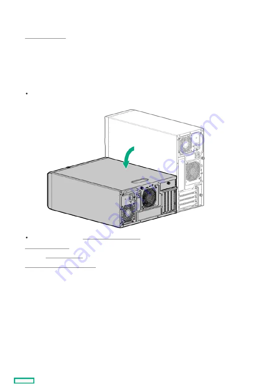
4. Do one of the following:
If the server is in tower mode, place the server on a flat, level surface with the access panel facing up.
If the server is in rack mode, remove the server from the rack .
6. If installed, remove the air baffle .
7. Locate the battery on the system board .
8. Remove the system battery:
a. Use a small flat-bladed, nonconductive tool to press the battery latch (callout 1).
b. Remove the system battery from the socket (callout 2).
Removing and replacing the system battery
209
Содержание ProLiant ML30 Gen10 Plus
Страница 17: ...DIMM slot location The arrow points to the front of the server DIMM slot location 17 ...
Страница 27: ...Fan numbering Fan number Description 1 PCI fan optional 2 System fan 3 Heatsink fan Fan numbering 27 ...
Страница 37: ...7 Place the server on a flat level surface with the access panel facing up Remove the server from the rack 37 ...
Страница 40: ...Remove the access panel 40 ...
Страница 42: ...Remove the air baffle 42 ...
Страница 45: ...Remove a media drive 45 ...
Страница 53: ...11 Power up the server Install the server into the rack 53 ...
Страница 66: ...doors Rack warnings and cautions 66 ...
Страница 76: ...6 Install the server into the rack Install the rack rails and server tray 76 ...
Страница 88: ...SFF drive 4 Install the drive LFF drive SFF drive Installing a hot plug LFF SFF SAS or SATA drive 88 ...
Страница 104: ...For more information see the drive documentation The installation is complete Installing a SAS LTO tape drive 104 ...
Страница 140: ...Installing a DIMM 140 ...
Страница 163: ...The installation is complete Installing the M 2 SATA SSD enablement option 163 ...
Страница 170: ...Cabling This chapter includes cabling guidelines and diagrams for internal component cabling Cabling 170 ...
Страница 180: ...Energy pack cabling Energy pack cabling 180 ...
Страница 186: ...RDX backup system cabling 186 ...
Страница 188: ...Gold SATA connector of the SATA power Y cable Color Description Optical drive cabling 188 ...
Страница 190: ...Fan cabling PCI fan cabling System fan cabling Heatsink fan cabling Fan cabling 190 ...
Страница 191: ...PCI fan cabling PCI fan cabling 191 ...
Страница 192: ...System fan cabling System fan cabling 192 ...
Страница 193: ...Heatsink fan cabling Heatsink fan cabling 193 ...
Страница 196: ...Power supply cabling Non hot plug power supply cabling Flexible Slot power supply cabling Power supply cabling 196 ...
Страница 204: ...Troubleshooting NMI functionality Troubleshooting resources Troubleshooting 204 ...
Страница 216: ...Ukraine RoHS material content declaration Ukraine RoHS material content declaration 216 ...


