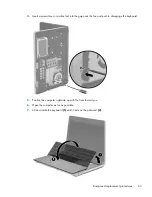
3.
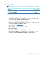
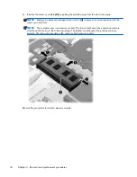
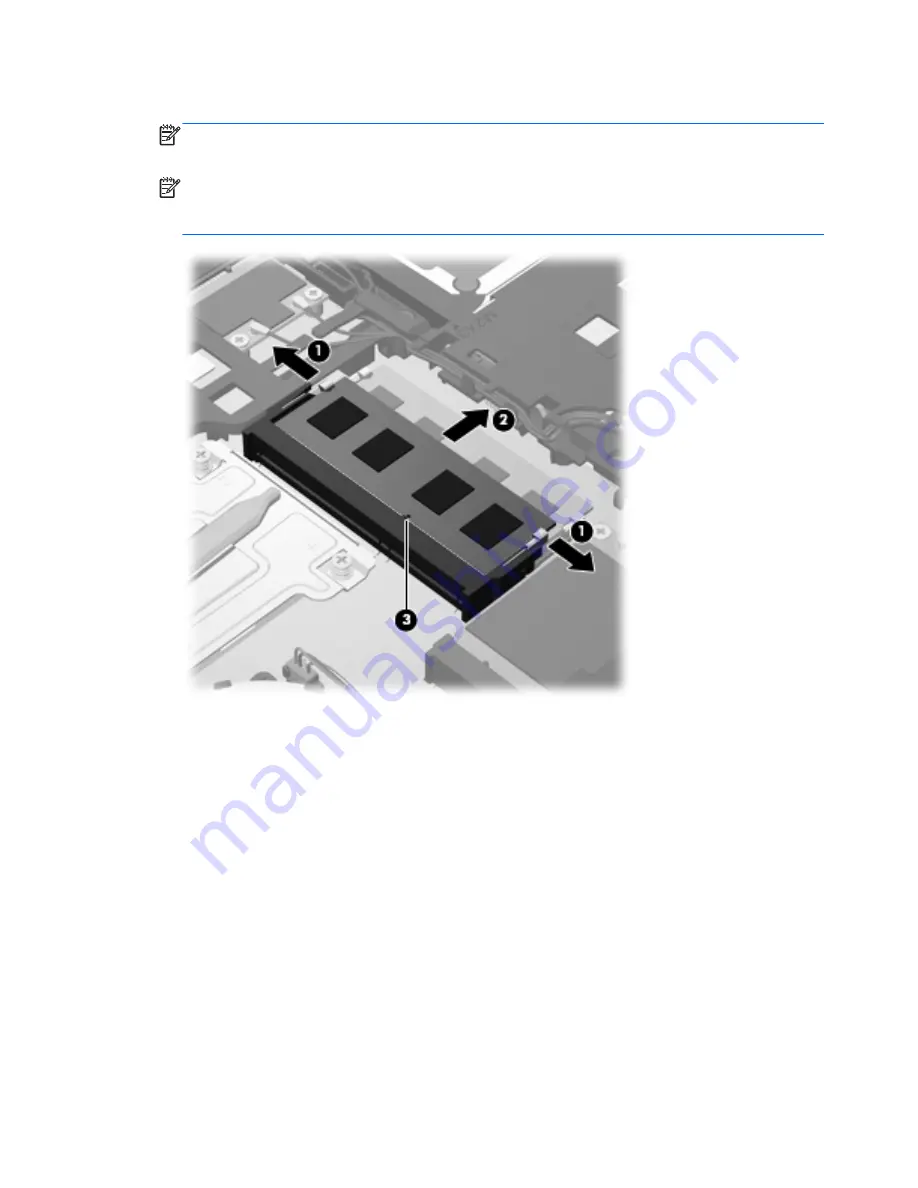
Remove the memory module
(2)
by pulling the module away from the slot at an angle.
NOTE:
Memory modules are designed with a notch
(3)
to prevent incorrect insertion into the
memory module slot.
NOTE:
The computer uses two memory sockets. The top socket houses the expansion memory
module and is shown in the following image. The bottom socket houses the primary memory
module. The removal procedure is the same for both memory sockets.
Reverse this procedure to install a memory module.
54
Chapter 4 Removal and replacement procedures
Содержание ProBook 4430s
Страница 1: ...HP ProBook 4430s Notebook PC HP ProBook 4330s Notebook PC Maintenance and Service Guide ...
Страница 4: ...iv Safety warning notice ...
Страница 8: ...viii ...
Страница 29: ...Computer major components Computer major components 21 ...
Страница 83: ...Cable routing path top Cable routing path bottom Component replacement procedures 75 ...
Страница 150: ......

