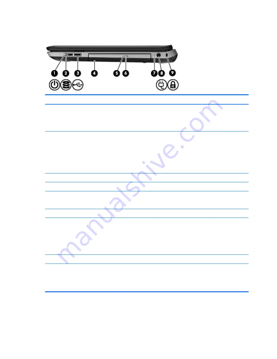
background image

Right side

Item

Component

Description

(1)

Power light

White: The computer is on.

Blinking white: The computer is in the Sleep state.

Off: The computer is off or in Hibernation.

(2)

Drive light

Blinking white: The hard drive is being accessed.

Amber: HP ProtectSmart Hard Drive Protection has
temporarily parked the hard drive.

NOTE:

For information on HP ProtectSmart

Hard Drive Protection, refer to the 

HP Notebook

Reference Guide

.

(3)

USB ports (2)

Connect optional USB devices.

(4)

Optical drive

Reads and writes to an optical disc.

(5)

Optical drive light

White: The optical drive is being accessed.

Amber: The optical drive is off.

(6)

Optical drive eject button

Ejects the optical disc.

(7)

AC adapter light

White: The computer is connected to external power
and the battery is fully charged.

Amber: The battery is charging.

Off: The computer is not connected to
external power.

(8)

Power connector

Connects an AC adapter.

(9)

Security cable slot

Attaches an optional security cable to the computer.

NOTE:

The security cable is designed to act as a

deterrent, but it may not prevent the computer from being
mishandled or stolen.

20

Chapter 2   External component identification

Содержание PAVILLION DV7

Страница 1: ...HP Pavilion dv7 Notebook PC Maintenance and Service Guide ...

Страница 2: ...ies Microsoft and Windows are U S registered trademarks of Microsoft Corporation SD Logo is a trademark of its proprietor The information contained herein is subject to change without notice The only warranties for HP products and services are set forth in the express warranty statements accompanying such products and services Nothing herein should be construed as constituting an additional warran...

Страница 3: ...w another hard surface such as an adjoining optional printer or a soft surface such as pillows or rugs or clothing to block airflow Also do not allow the AC adapter to contact the skin or a soft surface such as pillows or rugs or clothing during operation The device and the AC adapter comply with the user accessible surface temperature limits defined by the International Standard for Safety of Inf...

Страница 4: ...iv Safety warning notice ...

Страница 5: ...alog 22 Service tag 23 Computer major components 24 Display assembly subcomponents 33 Mass storage devices 34 Miscellaneous parts 35 Sequential part number listing 36 4 Removal and replacement procedures 46 Preliminary replacement requirements 46 Tools required 46 Service considerations 46 Plastic parts 46 Cables and connectors 46 Drive handling 47 Grounding guidelines 47 Electrostatic discharge d...

Страница 6: ...s 84 Power connector cable 86 System board 87 Fan heat sink assembly 91 Processor 95 Optical drive cable 99 Rear speakers 100 Subwoofer 102 Display assembly 103 5 Setup Utility BIOS and System Diagnostics 111 Using Setup Utility 111 Starting Setup Utility 111 Changing the language of Setup Utility 111 Navigating and selecting in Setup Utility 112 Displaying system information 112 Restoring factory...

Страница 7: ...1 Restoring using the restore media 122 Changing the computer boot order 122 Backing up and recovering your information 123 Using Windows Backup and Restore 124 Using Windows system restore points 124 When to create restore points 124 Create a system restore point 125 Restore to a previous date and time 125 8 Power cord set requirements 126 Requirements for all countries 126 Requirements for speci...

Страница 8: ...viii ...

Страница 9: ...5 W AMD A6 3400M 2 30 GHz processor 1 40 GHz FSB 4 0 MB L2 cache quad core 35 W AMD A4 3310MX 2 50 GHz processor 2 10 GHz FSB 2 0 MB L2 cache dual core 45 W AMD A4 3300M 2 50 GHz processor 1 90 GHz FSB 2 0 MB L2 cache dual core 35 W AMD E2 3000M 2 40 GHz processor 1 80 GHz FSB 4 0 MB L2 cache quad core 35 W AMD Athlon II N370 2 50 GHz processor 1 0 MB L2 cache 1066 MHz FSB 3 2 GT second dual core ...

Страница 10: ... MB L2 cache 1066 MHz FSB 3 6 GT second dual core 35 W AMD Turion II N560 2 50 GHz processor 2 0 MB L2 cache 1066 MHz FSB 3 6 GT second dual core 35 W Intel Quad Core i7 2820QM 2 30 GHz turbo up to 3 10 GHz processor 1600 MHz FSB 8 MB L3 cache 45 W Intel Quad Core i7 2720QM 2 20 GHz turbo up to 3 00 GHz processor 1600 MHz FSB 6 MB L3 cache 45 W Intel Quad Core i7 2630QM 2 00 GHz turbo up to 2 90 G...

Страница 11: ... i3 2330M 2 20 GHz processor 3 0 MB L3 cache 35 W Intel Dual Core i3 2310M 2 10 GHz processor 3 MB L3 cache 35 W Intel Pentium B950 TJ85 2 10 GHz processor 2 0 MB L3 cache dual core 35 W Intel Pentium B940 TJ85 2 00 GHz processor 2 0 MB L3 cache dual core 35 W Chipset ATI RS880M AMD M880G with ATI Mobility Radeon HD 4250 Northbridge AMD RS880MD Southbridge AMD SB820M Intel HM65 Express chipset 3 ...

Страница 12: ...graphics on computer models equipped with an AMD A8 or A6 processor supports bus alive chip off BACO dual graphics HD decode DX11 and HDMI AMD RadeonT HD 6645G2 graphics on computer models equipped with an AMD A8 processor supports BACO dual graphics HD decode DX11 and HDMI AMD RadeonT HD 6545G2 graphics on computer models equipped with an AMD A6 processor supports BACO dual graphics HD decode DX1...

Страница 13: ...d HDMI Panel 17 3 in WVA AntiGlare 1920 1080 full high definition FHD light emitting diode LED display typical brightness 300 nits 17 3 in SVA BrightView 1600 900 high definition HD LED display typical brightness 200 nits All display assemblies include 2 wireless local area network WLAN antenna cables Supports 16 9 ultra wide aspect ratio Supports low voltage differential signalling LVDS Lighted l...

Страница 14: ...7 in and 7 0 mm 28 in thicknesses Customer accessible Accelerometer hard drive protection support Supports up to 2 hard drives Supports 160 GB solid state drive solid state drive Serial ATA Supports 500 GB 7200 rpm 9 5 mm hard drive 160 GB solid state drive combination Supports the following double hard drive configurations 2 TB 1 TB 5400 rpm 12 7 mm 2 1500 GB 750 GB 7200 rpm 9 5 mm 2 1500 GB 750 ...

Страница 15: ...ro power optical drive computer models equipped with AMD Athlon Phenom and Turion processors Audio and video Dual array digital microphones with appropriate beam forming echo cancellation noise suppression software HD audio Quad speakers HP Beats audio HP triple bass reflex subwoofer HP TrueVision low light HD VGA webcam fixed no tilt with activity LED 1280 800 by 30 frames per second Ethernet Int...

Страница 16: ... 802 11b g n 1 1 WiFi and Bluetooth 4 0LE Combo Adapter Support for the following WLAN formats Atheros AR9002WB 1NGB 802 11b g n 1 1 WiFi and Bluetooth 2 1EDR Combo Adapter BT3 0 HS ready Realtek 8188BC8 802 11a b g n 2 2 WiFi and Bluetooth 3 0 HS Combo Adapter Realtek 8188GN 802 11b g n 1 1 WiFi Adapter Support for the following WLAN formats Intel Centrino Advanced N 6230 Intel Centrino Wireless ...

Страница 17: ...and style keyboard with full numeric keypad TouchPad with multi touch gestures 2 finger scrolling and pinch zoom enabled Taps enabled by default Power requirements 90W slim travel AC adapter with localized cable plug support 3 wire plug with ground pin supports 3 pin DC connector 65W slim travel AC adapter with localized cable plug support 3 wire plug with ground pin supports 3 pin DC connector 12...

Страница 18: ...ped with an Intel processor Operating system Preinstalled Windows 7 Home Basic Windows 7 Home Premium Windows 7 Professional RedFlag FreeDOS Serviceability End user replaceable parts AC adapter Battery Hard drives 2 Memory modules 2 Optical drive WLAN module 10 Chapter 1 Product description ...

Страница 19: ...2 External component identification 11 ...

Страница 20: ...to exit Sleep When the computer is in Hibernation press the button briefly to exit Hibernation If the computer has stopped responding and Windows shutdown procedures are ineffective press and hold the power button for at least 5 seconds to turn off the computer To learn more about your power settings select Start Control Panel System and Security Power Options or refer to the HP Notebook Reference...

Страница 21: ...der select models only Allows a fingerprint logon to Windows instead of a password logon Keys Item Component Description 1 esc key Displays system information when pressed in combination with the fn key 2 fn key Executes frequently used system functions when pressed in combination with the b key the esc key or the num lk key 3 Windows logo key Displays the Windows Start menu Top 13 ...

Страница 22: ...ct Start Programs Beats Audio Control Panel Listening Experience or Select Start Control Panel Hardware and Sound Beats Audio Control Panel Listening Experience 5 Windows applications key Displays a shortcut menu for items beneath the pointer 6 Integrated numeric keypad When the keypad has been enabled the keys can be used like an external numeric keypad 7 num lk key Enables disables the integrate...

Страница 23: ...nd is on Amber Computer sound is off 4 Wireless light White An integrated wireless device such as a wireless local area network WLAN device and or a Bluetooth device is on Amber All wireless devices are off 5 TouchPad on light On The TouchPad is on Off The TouchPad is off 6 TouchPad off light Off The TouchPad is on On The TouchPad is off 7 Fingerprint reader light select models only White The fing...

Страница 24: ... icon to turn the TouchPad on and off 3 TouchPad zone Moves the pointer and selects or activates items on the screen 4 Left TouchPad button Functions like the left button on an external mouse 5 TouchPad on light On The TouchPad is on Off The TouchPad is off 6 Right TouchPad button Functions like the right button on an external mouse 16 Chapter 2 External component identification ...

Страница 25: ...still photographs To use the webcam select Start All Programs CyberLink YouCam CyberLink YouCam The antennas are not visible from the outside of the computer For optimal transmission keep the areas immediately around the antennas free from obstructions To see wireless regulatory notices refer to the section of the Regulatory Safety and Environmental Notices that applies to your country or region T...

Страница 26: ...t Item Component Description 1 Speakers 2 Produce sound 2 Digital Media Slot Supports the following digital card formats MultiMediaCard Secure Digital SD Card 18 Chapter 2 External component identification ...

Страница 27: ...3 0 devices and provide enhanced USB power performance only on computer models equipped with an AMD A8 A6 A4 or E2 processor NOTE The SuperSpeed USB ports are also compatible with USB 1 0 and 2 0 devices 6 Audio in microphone jack Connects an optional computer headset microphone stereo array microphone or monaural microphone 7 Audio out headphone jacks 2 Produce sound when connected to optional po...

Страница 28: ...ical drive Reads and writes to an optical disc 5 Optical drive light White The optical drive is being accessed Amber The optical drive is off 6 Optical drive eject button Ejects the optical disc 7 AC adapter light White The computer is connected to external power and the battery is fully charged Amber The battery is charging Off The computer is not connected to external power 8 Power connector Con...

Страница 29: ...tery from the battery bay and releases the hard drive memory module compartment cover 5 Hard drive bay Holds the hard drive and wireless LAN WLAN device and contains the memory module slots CAUTION To prevent an unresponsive system replace the wireless module only with a wireless module authorized for use in the computer by the governmental agency that regulates wireless devices in your country or...

Страница 30: ...3 Illustrated parts catalog 22 Chapter 3 Illustrated parts catalog ...

Страница 31: ...to the front of the computer 2 Serial number s n This is an alphanumeric identifier that is unique to each product 3 Part number Product number p n This number provides specific information about the product s hardware components The part number helps a service technician to determine what components and parts are needed 4 Warranty period This number describes the duration of the warranty period f...

Страница 32: ...Computer major components 24 Chapter 3 Illustrated parts catalog ...

Страница 33: ...es 639397 001 NOTE For more display assembly spare part information see Display assembly subcomponents on page 33 2 Keyboard includes keyboard cable For use with all computer models For use in Belgium 639396 A41 For use in Canada 639396 121 For use in the Czech Republic 639396 221 For use in Denmark Finland and Norway 639396 DH1 For use in France 639396 051 For use in Germany 639396 041 For use in...

Страница 34: ...cable 646434 001 Cable Kit includes 639402 001 9 Power connector cable Not illustrated Fingerprint reader board cable Power button board cable SD Card reader board cable TouchPad cable TouchPad button board cables USB board cable 10 Bluetooth module for use only with computer models equipped with an Intel processor does not include cable EDR v 4 0 655792 001 EDR v 3 0 537921 001 11 Bluetooth modul...

Страница 35: ...with computer models equipped with the Intel HM65 chipset an Intel Dual Core processor and a graphics subsystem with 2 0 GB of discrete memory 655489 001 For use only with computer models equipped with the Intel HM65 chipset an Intel Quad Core processor and a graphics subsystem with UMA memory 656292 001 For use only with computer models equipped with the HM65 chipset an Intel Dual Core processor ...

Страница 36: ...rete memory 641493 001 For use only with computer models equipped with an Intel processor and a graphics subsystem with UMA memory 641492 001 14 Processor includes replacement thermal material AMD A8 3530MX 2 60 GHz processor 1 90 GHz FSB 4 0 MB L2 cache quad core 45 W 653364 001 AMD A8 3510MX 2 50 GHz processor 1 80 GHz FSB 4 0 MB L2 cache quad core 45 W 653358 001 AMD A8 3500M 2 40 GHz processor...

Страница 37: ... 1600 MHz FSB 8 MB L3 cache 45 W 634694 001 Intel Quad Core i7 2720QM 2 20 GHz turbo up to 3 00 GHz processor 1600 MHz FSB 6 MB L3 cache 45 W 631254 001 Intel Quad Core i7 2630QM 2 00 GHz turbo up to 2 90 GHz processor 1600 MHz FSB 6 MB L3 cache 45 W 635501 001 Intel Dual Core i7 2620M 2 70 GHz turbo up to 3 40 GHz processor 1333 MHz FSB 4 MB L3 cache 35 W 631252 001 Intel Dual Core i5 2540M 2 60 ...

Страница 38: ... and cable 639393 001 18 Base enclosure includes battery release latch and 4 rubber feet For use only with computer models equipped with an Intel processor includes openings for 3 USB ports 639399 001 For use only with computer models equipped with an AMD processor includes openings for 2 USB ports 657988 001 19 Hard drive 2 2 5 in SATA does not include bracket connector cable shield or screws 1 T...

Страница 39: ...0 AHr LI 593562 001 6 cell 55 WHr 2 55 AHr LI 593554 001 22 RTC battery includes cable and double sided tape 640902 001 23 Memory modules 2 DDR3 10600 1333 MHz 8 GB for use only with computer models equipped with an Intel processor 634091 001 4 GB 621569 001 2 GB 621565 001 1 GB 639736 001 24 WLAN module For use with all computer models Atheros 9485GN 802 11b g n 1 1 WiFi and 3012 Bluetooth 4 0 Co...

Страница 40: ...er 602993 001 Realtek 8188GN 802 11b g n 1 1 WiFi Adapter 640926 001 For use only with computer models equipped with an Intel processor Intel Centrino Advanced N 6230 631956 001 Intel Centrino Wireless N 1000 802 11b g n 1 2 WLAN module 593530 001 Intel Centrino Wireless N WiMAX 6150 633817 001 25 Service cover available in the Plastics Kit spare part number 641305 001 32 Chapter 3 Illustrated par...

Страница 41: ...View HD LED LVDS display panel for use with all computer models 641629 001 4 Display Cable Kit includes display panel cable and webcam microphone module cable 640900 001 5 Webcam microphone module 639387 001 6 Antenna Kit includes left and right wireless antenna cables and transceivers 639401 001 7 Display enclosure In steel gray finish 649946 001 In regular finish 639400 001 Display Rubber Kit no...

Страница 42: ...with an Intel processor 608218 001 320 GB 7200 rpm 634862 001 and 641672 001 250 GB 7200 rpm 634861 001 and 635225 001 Hard Drive Hardware Kit includes 641306 001 2a Primary hard drive connector cable 2b Primary hard drive bracket 4a Secondary hard drive connector cable 4b Secondary hard drive bracket Screws not illustrated 3 160 GB solid state drive does not include bracket connector cable shield...

Страница 43: ... Optical drive bay space saver not illustrated 659624 001 Optical Drive Hardware Kit includes 641549 001 6a Optical drive cable 6b Optical drive bracket 6c Optical drive bezel Screws not illustrated Miscellaneous parts Component Spare part number HP Smart AC adapter 90 W PFC RC V HP Smart AC adapter for use with all computer models 609940 001 65 W RC V HP Smart AC adapter for use only with compute...

Страница 44: ...541 004 Remote control full function with teletext 490371 001 Power cord for use with all computer models in North America 3 pin black 1 83 meter 490371 011 Power cord for use only with computer models equipped with an Intel processor in Australia 3 pin black 1 83 meter 490371 021 Power cord for use with all computer models in Europe 3 pin black 1 83 meter 490371 031 Power cord for use with all co...

Страница 45: ... WLAN module for use only with computer models equipped with an Intel processor 593554 001 6 cell 55 WHr 2 55 AHr Li battery 593562 001 6 cell 62 WHr 2 80 AHr Li battery 593836 001 Broadcom 4313 802 11b g n 1 1 WiFi Adapter for use with all computer models 600370 001 Broadcom 4313 802 11b g n 1 1 WiFi and 2070 Bluetooth 2 1 EDR Combo adapter BT3 0HS ready for use with all computer models 602993 00...

Страница 46: ...2 60 GHz turbo up to 3 30 GHz processor 1333 MHz FSB 3 MB L3 cache 35 W includes replacement thermal material 631956 001 Intel Centrino Advanced N 6230 for use only with computer models equipped with an Intel processor 633252 001 750 GB 7200 rpm hard drive 2 5 in SATA does not include bracket connector cable shield or screws 633817 001 Intel Centrino Wireless N WiMAX 6150 for use only with compute...

Страница 47: ... L3 cache 35 W includes replacement thermal material 638039 001 Intel Dual Core i5 2410M 2 30 GHz turbo up to 2 90 GHz processor 3 MB L3 cache 35 W includes replacement thermal material 638974 001 1 TB 5400 rpm hard drive 2 5 in SATA does not include bracket connector cable shield or screws 639387 001 Webcam microphone module 639388 001 Top cover in regular finish includes TouchPad and TouchPad ca...

Страница 48: ...or use with all computer models in the Czech Republic includes keyboard cable 639396 251 Keyboard for use with all computer models in Russia includes keyboard cable 639396 261 Keyboard for use only with computer models equipped with an Intel processor in Bulgaria includes keyboard cable 639396 281 Keyboard for use only with computer models equipped with an Intel processor in Thailand includes keyb...

Страница 49: ...z 640427 001 Fingerprint reader board includes bracket but does not include cable 640456 001 Thermal Material Kit for use only with computer models equipped with an AMD Athlon Phenom or Turion processor and a graphics subsystem with UMA memory includes replacement thermal pads and paste 640457 001 Thermal Material Kit for use only with computer models equipped with an AMD Athlon Phenom or Turion p...

Страница 50: ...ly with computer models equipped with an AMD processor and a graphics subsystem with discrete memory includes replacement thermal pads and paste 641582 001 Display Screw Kit 641629 001 17 3 in BrightView HD LED LVDS display panel 641672 001 320 GB 7200 rpm hard drive 2 5 in SATA does not include bracket connector cable shield or screws 645384 001 System board for use only with computer models equi...

Страница 51: ...e 35 W includes replacement thermal material 653349 001 AMD A6 3400M 2 30 GHz processor 1 40 GHz FSB 4 0 MB L2 cache quad core 35 W includes replacement thermal material 653350 001 AMD A8 3500M 2 40 GHz processor 1 50 GHz FSB 4 0 MB L2 cache quad core 35 W includes replacement thermal material 653351 001 AMD E2 3000M 2 40 GHz processor 1 80 GHz FSB 4 0 MB L2 cache quad core 35 W includes replaceme...

Страница 52: ... microphones and wireless antenna transceivers and cables 656296 001 17 3 in AntiGlare FHD LED display assembly in steel gray finish for use only with computer models equipped with an Intel processor includes webcam two microphones and wireless antenna transceivers and cables 656297 001 17 3 in AntiGlare FHD LED display panel for use only with computer models equipped with an Intel processor 65732...

Страница 53: ...with an Intel dual core processor the 6770 graphics subsystem and 1 0 GB of discrete video memory BACO includes replacement thermal material 659624 001 Optical drive bay space saver 659875 001 DVD RW and CD RW Super Multi Double Layer Combo Drive with LightScribe for use only with computer models equipped with an AMD processor 659876 001 Blu ray ROM with LightScribe DVD R RW Super Multi Double Lay...

Страница 54: ...sembly can damage plastic parts Use care when handling the plastic parts Apply pressure only at the points designated in the maintenance instructions Cables and connectors CAUTION When servicing the computer be sure that cables are placed in their proper locations during the reassembly process Improper cable placement can damage the computer Cables must be handled with extreme care to avoid damage...

Страница 55: ...posing an internal hard drive to products that have magnetic fields such as monitors or speakers Avoid exposing a drive to temperature extremes or liquids If a drive must be mailed place the drive in a bubble pack mailer or other suitable form of protective packaging and label the package FRAGILE Grounding guidelines Electrostatic discharge damage Electronic components are sensitive to electrostat...

Страница 56: ...following table shows how humidity affects the electrostatic voltage levels generated by different activities CAUTION A product can be degraded by as little as 700 V Typical electrostatic voltage levels Relative humidity Event 10 40 55 Walking across carpet 35 000 V 15 000 V 7 500 V Walking across vinyl floor 12 000 V 5 000 V 3 000 V Motions of bench worker 6 000 V 800 V 400 V Removing DIPS from p...

Страница 57: ...nd and that proper materials are selected to avoid static charging When grounding is not possible use an ionizer to dissipate electric charges Workstation guidelines Follow these grounding workstation guidelines Cover the workstation with approved static shielding material Use a wrist strap connected to a properly grounded work surface and use properly grounded tools and equipment Use conductive f...

Страница 58: ... between the operator and ground To be effective the conductive must be worn in contact with the skin The following grounding equipment is recommended to prevent electrostatic damage Antistatic tape Antistatic smocks aprons and sleeve protectors Conductive bins and other assembly or soldering aids Nonconductive foam Conductive tabletop workstations with ground cords of one megohm resistance Static...

Страница 59: ...iption provided on the service tag When ordering parts or requesting information provide the computer serial number and model description provided on the service tag Item Description Function 1 Product name This is the product name affixed to the front of the computer 2 Serial number s n This is an alphanumeric identifier that is unique to each product 3 Part number Product number p n This number ...

Страница 60: ...cription Spare part number 9 cell 100 WHr 3 00 AHr LI 636631 001 6 cell 62 WHr 2 80 AHr LI 593562 001 6 cell 55 WHr 2 55 AHr LI 593554 001 Before disassembling the computer follow these steps 1 Shut down the computer If you are unsure whether the computer is off or in Hibernation turn the computer on and then shut it down through the operating system 2 Disconnect all external devices connected to ...

Страница 61: ...t Description Spare part number For use with all computer models Blu ray Disc R RW with SuperMulti DVD R RW Double Layer Drive with LightScribe 659876 001 DVD RW Double Layer LightScribe SuperMulti Drive 659875 001 For use only with computer models equipped with an AMD processor Blu ray Disc R RW with SuperMulti DVD R RW Double Layer Drive with LightScribe 641850 001 DVD RW Double Layer LightScrib...

Страница 62: ...tem 2 Disconnect all external devices connected to the computer 3 Disconnect the power from the computer by first unplugging the power cord from the AC outlet and then unplugging the AC adapter from the computer 4 Remove the battery see Battery on page 52 Remove the optical drive 1 Slide the release latch 1 to release the service cover from the computer 2 Lift the rear edge of the service cover 2 ...

Страница 63: ...1 to release the optical drive 6 Remove the optical drive 2 from the computer 7 If it is necessary to replace the optical drive bracket position the optical drive with the rear panel toward you 8 Remove the two Phillips PM2 0 4 0 screws 1 that secure the bracket to the optical drive Component replacement procedures 55 ...

Страница 64: ...hard drives The primary hard drive is installed in the right hard drive bay The secondary hard drive is installed in the left hard drive bay Description Spare part number 1 TB 5400 rpm 638974 001 750 GB 7200 rpm 633252 001 750 GB 5400 rpm 634250 001 640 GB 7200 rpm 621046 001 500 GB 7200 rpm for use only with computer models equipped with an Intel processor 608218 001 320 GB 7200 rpm 634862 001 an...

Страница 65: ... page 52 5 Remove the service cover see Optical drive on page 53 Remove the hard drive NOTE Steps 1 through 3 apply to the primary hard drive See steps 4 through 7 for secondary hard drive removal information 1 Disconnect the hard drive cable 1 from the system board 2 Remove the four Philllips PM2 5 5 0 screws 2 that secure the hard drive to the computer 3 Remove the hard drive 3 4 Disconnect the ...

Страница 66: ...ce the hard drive bracket or hard drive connector cable a Remove the four Phillips PM3 0 4 0 screws 1 that secure the hard drive bracket to the hard drive b Remove the hard drive bracket 2 from the hard drive 58 Chapter 4 Removal and replacement procedures ...

Страница 67: ...nnector cable 3 from the hard drive NOTE The hard drive connector cable used on the secondary hard drive has a longer cable Reverse this procedure to reassemble and install the mass storage device Component replacement procedures 59 ...

Страница 68: ... power from the computer by first unplugging the power cord from the AC outlet and then unplugging the AC adapter from the computer 4 Remove the battery see Battery on page 52 5 Remove the service cover see Optical drive on page 53 Remove the RTC battery 1 Disconnect the RTC battery cable 1 from the system board 2 Release the clips 2 built into the base enclosure that secure the RTC battery 3 Remo...

Страница 69: ... 001 Before removing a memory module follow these steps 1 Shut down the computer If you are unsure whether the computer is off or in Hibernation turn the computer on and then shut it down through the operating system 2 Disconnect all external devices connected to the computer 3 Disconnect the power from the computer by first unplugging the power cord from the AC outlet and then unplugging the AC a...

Страница 70: ...n 1 1 WiFi and 20702 Bluetooth 4 0 Combo Adapter 657325 001 Ralink RT3090BC4 802 11b g n 1 1 WiFi and Bluetooth 2 1 EDR Combo adapter BT3 0HS ready 630705 001 Ralink 5390GN 802 11b g n 1 1 WiFi Adapter 630703 001 Realtek RTL8188CE 802 11b g n 1 1 WiFi and Bluetooth 4 0LE Combo Adapter 656119 001 For use only with computer models equipped with an AMD processor Atheros AR9002WB 1NGB 802 11b g n 1 1 ...

Страница 71: ...AN module follow these steps 1 Shut down the computer If you are unsure whether the computer is off or in Hibernation turn the computer on and then shut it down through the operating system 2 Disconnect all external devices connected to the computer 3 Disconnect the power from the computer by first unplugging the power cord from the AC outlet and then unplugging the AC adapter from the computer 4 ...

Страница 72: ...le by pulling the module away from the slot at an angle NOTE If the WLAN antennas are not connected to the terminals on the WLAN module the protective sleeves must be installed on the antenna connectors as shown in the following illustration Reverse this procedure to install the WLAN module 64 Chapter 4 Removal and replacement procedures ...

Страница 73: ...United States 639396 001 For use only with computer models equipped with an Intel processor For use in Saudi Arabia 639396 171 For use in Bulgaria 639396 261 For use in South Korea 639396 AD1 For use in India 639396 D61 For use in Taiwan 639396 AB1 For use in Israel 639396 BB1 For use in Thailand 639396 281 For use in Japan 639396 291 For use in Turkey 639396 141 Before removing the keyboard follo...

Страница 74: ...omputer on its right side 3 Open the computer 4 Insert a screw driver or similar thin tool into the keyboard screw hole and then press on the back of the keyboard until the keyboard disengages from the computer 5 Turn the computer right side up with the front toward you 66 Chapter 4 Removal and replacement procedures ...

Страница 75: ...rd cable connector is accessible 7 Release the zero insertion force ZIF connector 1 to which the keyboard cable is attached and then disconnect the keyboard cable 2 from the system board 8 Remove the keyboard Reverse this procedure to install the keyboard Component replacement procedures 67 ...

Страница 76: ...from the AC outlet and then unplugging the AC adapter from the computer 4 Remove the battery see Battery on page 52 and then remove the following components Optical drive see Optical drive on page 53 Hard drive see Hard drive on page 56 Keyboard see Keyboard on page 65 When replacing the top cover be sure that the following components are removed from the defective top cover and installed on the r...

Страница 77: ...ne Phillips PM2 5 7 0 screw in the rear left corner of the base enclosure 2 Three Philllips PM2 5 3 0 screws in the optical drive bay 3 Two Phillips PM2 5 9 0 screws on the right side of the base enclosure 5 Turn the computer right side up with the front toward you 6 Open the computer Component replacement procedures 69 ...

Страница 78: ...der board cable 4 USB board cable 8 Remove the two Phillips PM2 5 5 0 screws that secure the top cover to the computer NOTE As you prepare to release the top cover make sure the USB board 2 cable feeds freely through the opening 3 in the top cover 9 Lift the rear edge of the top cover 1 until the left and right sides disengage from the base enclosure 70 Chapter 4 Removal and replacement procedures...

Страница 79: ...10 Remove the top cover 2 Reverse this procedure to install the top cover Component replacement procedures 71 ...

Страница 80: ...ed to the computer 3 Disconnect the power from the computer by first unplugging the power cord from the AC outlet and then unplugging the AC adapter from the computer 4 Remove the battery see Battery on page 52 and then remove the following components Optical drive see Optical drive on page 53 Hard drive see Hard drive on page 56 Keyboard see Keyboard on page 65 Top cover see Top cover on page 68 ...

Страница 81: ...3 Remove the fingerprint reader board bracket 3 board 4 and cable Reverse this procedure to install the fingerprint reader board bracket and cable Component replacement procedures 73 ...

Страница 82: ...r from the computer by first unplugging the power cord from the AC outlet and then unplugging the AC adapter from the computer 4 Remove the battery see Battery on page 52 and then remove the following components Optical drive see Optical drive on page 53 Hard drive see Hard drive on page 56 Keyboard see Keyboard on page 65 Top cover see Top cover on page 68 Remove the power button board 1 Turn the...

Страница 83: ...5 Remove the power button board and cable 4 Reverse this procedure to install the power button board Component replacement procedures 75 ...

Страница 84: ...irst unplugging the power cord from the AC outlet and then unplugging the AC adapter from the computer 4 Remove the battery see Battery on page 52 and then remove the following components Optical drive see Optical drive on page 53 Hard drive see Hard drive on page 56 Keyboard see Keyboard on page 65 Top cover see Top cover on page 68 Remove the display lid switch board 1 Turn the top cover upside ...

Страница 85: ...lay lid switch board from the clips 3 built into the top cover 5 Remove the display lid switch board and cable Reverse this procedure to install the display lid switch board and cable Component replacement procedures 77 ...

Страница 86: ... 3 Disconnect the power from the computer by first unplugging the power cord from the AC outlet and then unplugging the AC adapter from the computer 4 Remove the battery see Battery on page 52 and then remove the following components Optical drive see Optical drive on page 53 Hard drive see Hard drive on page 56 Keyboard see Keyboard on page 65 Top cover see Top cover on page 68 Remove the SD Card...

Страница 87: ...3 Remove the SD Card reader board 3 and cable Reverse this procedure to install the SD Card reader board and cable Component replacement procedures 79 ...

Страница 88: ...it down through the operating system 2 Disconnect all external devices connected to the computer 3 Disconnect the power from the computer by first unplugging the power cord from the AC outlet and then unplugging the AC adapter from the computer 4 Remove the battery see Battery on page 52 and then remove the following components Optical drive see Optical drive on page 53 Hard drive see Hard drive o...

Страница 89: ... base enclosure 4 Remove the Bluetooth module and cable 5 If it is necessary to replace the Bluetooth module cable disconnect the cable from the Bluetooth module Reverse this procedure to install the Bluetooth module and cable Component replacement procedures 81 ...

Страница 90: ...sconnect the power from the computer by first unplugging the power cord from the AC outlet and then unplugging the AC adapter from the computer 4 Remove the battery see Battery on page 52 and then remove the following components Optical drive see Optical drive on page 53 Hard drive see Hard drive on page 56 Keyboard see Keyboard on page 65 Top cover see Top cover on page 68 Remove the USB board 1 ...

Страница 91: ...3 Remove the USB board 3 and cable Reverse this procedure to install the USB board and cable Component replacement procedures 83 ...

Страница 92: ...computer by first unplugging the power cord from the AC outlet and then unplugging the AC adapter from the computer 4 Remove the battery see Battery on page 52 and then remove the following components Optical drive see Optical drive on page 53 Hard drive see Hard drive on page 56 Keyboard see Keyboard on page 65 Top cover see Top cover on page 68 USB board see USB board on page 82 Remove the front...

Страница 93: ...er to the base enclosure 4 Rotate the front left speaker 1 clockwise to release it from under the system board 5 Remove the front left speaker 2 6 Remove the front right speaker 3 Reverse this procedure to install the front speakers and cables Component replacement procedures 85 ...

Страница 94: ...g the AC adapter from the computer 4 Remove the battery see Battery on page 52 and then remove the following components Optical drive see Optical drive on page 53 Hard drive see Hard drive on page 56 Keyboard see Keyboard on page 65 Top cover see Top cover on page 68 Remove the power connector cable 1 Release the power connector cable from the clips 1 built into the base enclosure 2 Disconnect the...

Страница 95: ...th UMA memory includes replacement thermal material 645384 001 For use only with computer models equipped with an Intel processor For use only with computer models equipped with the Intel HM65 chipset an Intel Quad Core processor and a graphics subsystem with 2 0 GB of discrete memory 655488 001 For use only with computer models equipped with the Intel HM65 chipset an Intel Dual Core processor and...

Страница 96: ...er models equipped with an AMD Athlon Phenom or Turion processor and a graphics subsystem with UMA memory 640456 001 For use only with computer models equipped with an Intel processor and a graphics subsystem with 2 GB of discrete memory 650801 001 For use only with computer models equipped with an Intel processor and a graphics subsystem with discrete memory 641493 001 For use only with computer ...

Страница 97: ...TC battery on page 60 Fan and heat sink see Fan heat sink assembly on page 91 Processor see Processor on page 95 Remove the system board 1 Close the computer 2 Turn the computer upside down with the front toward you 3 Disconnect the rear speaker cable 1 and the optical drive cable 2 from the system board 4 Turn the computer right side up with the front toward you 5 Open the computer Component repl...

Страница 98: ...le 7 Remove the five Phillips PM2 5 5 0 screws that secure the system board to the base enclosure 8 Flex the left side 1 of the base enclosure outward to allow the audio connectors 2 to clear the openings in the base enclosure 9 Lift the front edge of the system board 3 until it rests at an angle 90 Chapter 4 Removal and replacement procedures ...

Страница 99: ... 001 For use only with computer models equipped with an Intel processor and a graphics subsystem with 2 0 GB of discrete memory 653627 001 For use only with computer models equipped with an Intel processor and a graphics subsystem with UMA memory 653628 001 For use only with computer models equipped with an Intel processor 640903 001 NOTE To properly ventilate the computer allow at least 7 6 cm 3 ...

Страница 100: ...d see Keyboard on page 65 Top cover see Top cover on page 68 System board see System board on page 87 Remove the fan heat sink assembly 1 Disconnect the fan cable from the system board 2 Turn the system board upside down with the front toward you NOTE Steps 3 and 4 apply to computer models equipped with an AMD processor See steps 5 and 6 for fan heat sink assembly removal information for computer ...

Страница 101: ...an heat sink assembly processor and system board spare part kits Thermal paste is used on the processor 1 and the heat sink section 2 that services it A thermal pad is used on the Northbridge chip 3 and the heat sink section 4 that services it A thermal pad is used on the graphics subsystem chip 5 and the heat sink section 6 that services it only on computer models equipped with a graphics subsyst...

Страница 102: ...tach it 6 Remove the fan heat sink assembly 2 NOTE The thermal material must be thoroughly cleaned from the surfaces of the heat sink and the system board components each time the fan heat sink assembly is removed Replacement thermal material is included with the fan heat sink assembly processor and system board spare part kits A thermal pad is used on the capacitors 1 and the heat sink section 2 ...

Страница 103: ...l core 45 W 653356 001 AMD A4 3300M 2 50 GHz processor 1 90 GHz FSB 2 0 MB L2 cache dual core 35 W 653348 001 AMD E2 3000M 2 40 GHz processor 1 80 GHz FSB 4 0 MB L2 cache quad core 35 W 653351 001 AMD Athlon II N370 2 50 GHz processor 1 0 MB L2 cache 1066 MHz FSB 3 2 GT second dual core 35 W 634686 001 AMD Athlon II P340 2 20 GHz processor 1 0 MB L2 cache 1066 MHz FSB 3 2 GT second dual core 25 W ...

Страница 104: ... i7 2620M 2 70 GHz turbo up to 3 40 GHz processor 1333 MHz FSB 4 MB L3 cache 35 W 631252 001 Intel Dual Core i5 2540M 2 60 GHz turbo up to 3 30 GHz processor 1333 MHz FSB 3 MB L3 cache 35 W 631255 001 Intel Dual Core i5 2520M 2 50 GHz turbo up to 3 20 GHz processor 1333 MHz FSB 3 MB L3 cache 35 W 631253 001 Intel Dual Core i5 2430M 2 40 GHz SC turbo up to 3 00 GHz processor 3 0 MB L3 cache 35 W 65...

Страница 105: ...ptical drive on page 53 Hard drive see Hard drive on page 56 WLAN module see WLAN module on page 62 Keyboard see Keyboard on page 65 Top cover see Top cover on page 68 System board see System board on page 87 Fan heat sink assembly see Fan heat sink assembly on page 91 Remove the processor 1 Use a flat bladed screw driver 1 to turn the processor locking screw one half turn counterclockwise 2 until...

Страница 106: ...e it NOTE The gold triangle 4 on the processor must be aligned with the triangle icon embossed on the processor socket when you install the processor Reverse this procedure to install the processor 98 Chapter 4 Removal and replacement procedures ...

Страница 107: ...cord from the AC outlet and then unplugging the AC adapter from the computer 4 Remove the battery see Battery on page 52 and then remove the following components Optical drive see Optical drive on page 53 Hard drive see Hard drive on page 56 Keyboard see Keyboard on page 65 Top cover see Top cover on page 68 System board see System board on page 87 Remove the optical drive cable 1 Release the opti...

Страница 108: ...the power from the computer by first unplugging the power cord from the AC outlet and then unplugging the AC adapter from the computer 4 Remove the battery see Battery on page 52 and then remove the following components Optical drive see Optical drive on page 53 Hard drive see Hard drive on page 56 WLAN module see WLAN module on page 62 Keyboard see Keyboard on page 65 Top cover see Top cover on p...

Страница 109: ...the computer 4 Turn the computer right side up with the front toward you 5 Open the computer 6 Release the rear speaker cable from the clips 1 and the routing channel built into the base enclosure Remove the rear speaker 2 Reverse this procedure to install the rear speakers and cables Component replacement procedures 101 ...

Страница 110: ...er from the computer 4 Remove the battery see Battery on page 52 and then remove the following components Optical drive see Optical drive on page 53 Hard drive see Hard drive on page 56 WLAN module see WLAN module on page 62 Keyboard see Keyboard on page 65 Top cover see Top cover on page 68 System board see System board on page 87 Rear speakers see Rear speakers on page 100 Remove the rear subwoo...

Страница 111: ...n regular finish 639397 001 Before removing the display assembly follow these steps 1 Shut down the computer If you are unsure whether the computer is off or in Hibernation turn the computer on and then shut it down through the operating system 2 Disconnect all external devices connected to the computer 3 Disconnect the power from the computer by first unplugging the power cord from the AC outlet ...

Страница 112: ...port the display assembly when removing the following screws Failure to support the display assembly can result in damage to the display assembly and other computer components 2 Remove the six Phillips PM2 5 5 0 screws 2 and 3 that secure the display assembly to the computer NOTE The middle screw 3 on the left hinge secures the display panel cable ground loop to the hinge 3 Remove the display asse...

Страница 113: ...rews 2 that secure the display bezel to the display assembly b Flex the inside edges of the top edge 1 the left and right sides 2 and the bottom edge 3 of the display bezel until the bezel disengages from the display enclosure c Remove the display bezel 4 The display bezel is available using spare part number 639398 001 Component replacement procedures 105 ...

Страница 114: ...n Phillips PM2 5 5 0 screws that secure the display panel to the display enclosure b Lift the top edge of the display panel and then swing it up and forward until it rests upside down in front of the display enclosure 106 Chapter 4 Removal and replacement procedures ...

Страница 115: ...only with computer models equipped with an Intel processor 641629 001 17 3 in BrightView HD LED LVDS display panel for use with all computer models 6 If it is necessary to replace the webcam microphone module a Detach and release the webcam microphone module 1 as far as the webcam microphone module cable allows The webcam microphone module is attached to the display enclosure with double sided tap...

Страница 116: ...lay hinges to the display panel b Remove the display hinges 2 The display hinges include the display hinges and brackets and are available using spare part number 639403 001 8 If it is necessary to replace the display panel cable a Disconnect the display logo light cable 1 from the display panel cable b Release the display panel cable 2 from the clips 3 built into the display enclosure 108 Chapter...

Страница 117: ...01 9 If it is necessary to replace the wireless antenna cables and transceivers a Release the wireless antenna transceivers 1 from the display enclosure The wireless antenna transceivers are attached to the display enclosure with double sided tape b Release the wireless antenna cables from the clips 2 built into the display enclosure Component replacement procedures 109 ...

Страница 118: ... transceivers 3 The wireless antenna cables and transceivers are available in the Antenna Kit spare part number 639401 001 Reverse this procedure to reassemble and install the display assembly 110 Chapter 4 Removal and replacement procedures ...

Страница 119: ...ted to a USB port can be used with Setup Utility only if USB legacy support is enabled To start Setup Utility follow these steps 1 Turn on or restart the computer and then press esc while the Press the ESC key for Startup Menu message is displayed at the bottom of the screen 2 Press f10 to enter Setup Utility Changing the language of Setup Utility 1 Start Setup Utility 2 Use the arrow keys to sele...

Страница 120: ...ter Setup Utility To exit Setup Utility menus choose one of the following methods To exit Setup Utility menus without saving your changes click the Exit icon in the lower left corner of the screen and then follow the on screen instructions or Use the tab key and the arrow keys to select File Ignore Changes and Exit and then press enter To save your changes and exit Setup Utility menus click the Sa...

Страница 121: ...the computer restarts NOTE Your password settings and security settings are not changed when you restore the factory settings Exiting Setup Utility To exit Setup Utility and save your changes from the current session If the Setup Utility menus are not visible press esc to return to the menu display Then use the arrow keys to select Exit Exit Saving Changes and then press enter To exit Setup Utilit...

Страница 122: ...al power source During the download and installation follow these instructions Do not disconnect power from the computer by unplugging the power cord from the AC outlet Do not shut down the computer or initiate Sleep or Hibernation Do not insert remove connect or disconnect any device cable or cord 1 Windows 7 Select Start Help and Support Maintain Windows XP Select Start Help and Support and then...

Страница 123: ...his test analyzes the main computer components that are required to start the computer Run in test This test repeats the start up test and checks for intermittent problems that the start up test does not detect Hard disk test This test analyzes the physical condition of the hard drive and then checks all data in every sector of the hard drive If the test detects a damaged sector it attempts to mov...

Страница 124: ... A or 4 74 A Temperature Operating 5 C to 35 C 41 F to 95 F Nonoperating 20 C to 6 C 4 F to 140 F Relative humidity noncondensing Operating 10 to 90 Nonoperating 5 to 95 Maximum altitude unpressurized Operating 15 m to 3 048 m 50 ft to 10 000 ft Nonoperating 15 m to 12 192 m 50 ft to 40 000 ft NOTE Applicable product safety standards specify thermal limits for plastic surfaces The device operates ...

Страница 125: ...olors Up to 16 8 million Contrast ratio 200 1 typical Brightness 180 nits typical Pixel resolution Pitch 0 197 0 197 mm Format 1600 900 Configuration RGB vertical stripe Backlight LED Character display 80 25 Total power consumption varies by display 2 0 W Viewing angle 65 horizontal 50 vertical typical 17 3 inch display specifications 117 ...

Страница 126: ...Seek times typical read including setting Single track 2 ms 2 ms 1 5 ms 1 5 ms 1 5 ms 1 5 ms 1 5 ms Average read write 12 16 ms 12 16 ms 12 13 ms 11 13 ms 11 13 ms 11 13 ms 11 13 ms Maximum 21 ms 21 ms 24 ms 22 ms 22 ms 22 ms 22 ms Logical blocks 1 953 525 168 1 465 149 168 1 250 263 728 976 773 1 68 628 142 4 48 488 397 1 68 312 581 8 08 Disk rotational speed 5400 rpm 7200 and 5400 rpm 7200 and 5...

Страница 127: ...overy Manager HP recommends that you use this software to create either a set of recovery discs or a recovery flash drive immediately after software setup If for some other reason you need to restore your system this can be achieved using the HP Recovery partition select models only without the need for recovery discs or a recovery flash drive To check for the presence of a recovery partition clic...

Страница 128: ...ical drive it must be connected directly to a USB port on the computer not to a USB port on an external device such as a USB hub Guidelines Purchase high quality DVD R DVD R DVD R DL or DVD R DL discs NOTE Read write discs such as CD RW DVD RW double layer DVD RW and BD RE rewritable Blu ray discs are not compatible with the Recovery Manager software The computer must be connected to AC power duri...

Страница 129: ...ing Recovery Manager Recovery Manager restores only software that was preinstalled at the factory Software not provided with this computer must be downloaded from the manufacturer s Web site or reinstalled from the disc provided by the manufacturer Restoring using the dedicated recovery partition select models only When using the dedicated recovery partition there is an option to back up pictures ...

Страница 130: ...3 Press f9 at system bootup 4 Select the optical drive or the flash drive 5 Follow the on screen instructions Changing the computer boot order To change the boot order for recovery discs 1 Restart the computer 2 Press esc while the computer is restarting and then press f9 for boot options 3 Select Internal CD DVD ROM Drive from the boot options window To change the boot order for recovery flash dr...

Страница 131: ...riodically Before the computer is repaired or restored Before you add or modify hardware or software Guidelines Create system restore points using the Windows System Restore feature and periodically copy them to an optical disc or an external hard drive For more information on using system restore points refer to Using Windows system restore points Store personal files in the Documents library and...

Страница 132: ...anging Windows settings Refer to Help and Support for more information Using Windows system restore points A system restore point allows you to save and name a snapshot of your hard drive at a specific point in time You can then recover back to that point if you want to reverse subsequent changes NOTE Recovering to an earlier restore point does not affect data files saved or e mails created since ...

Страница 133: ...estore to a previous date and time To revert to a restore point created at a previous date and time when the computer was functioning optimally follow these steps 1 Select Start Control Panel System and Security System 2 In the left pane click System Protection 3 Click the System Protection tab 4 Click System Restore 5 Follow the on screen instructions Backing up and recovering your information 12...

Страница 134: ...uirements are applicable to all countries and regions The length of the power cord set must be at least 1 5 m 5 0 ft and no more than 2 0 m 6 5 ft All power cord sets must be approved by an acceptable accredited agency responsible for evaluation in the country or region where the power cord set will be used The power cord sets must have a minimum current capacity of 10 amps and a nominal voltage r...

Страница 135: ...st be a two pole grounding type with a NEMA 5 15P 15 A 125 V or NEMA 6 15P 15 A 250 V configuration 3 The appliance coupler flexible cord and wall plug must bear a T mark and registration number in accordance with the Japanese Dentori Law The flexible cord must be Type VCT or VCTF 3 conductor 1 00 mm conductor size The wall plug must be a two pole grounding type with a Japanese Industrial Standard...

Страница 136: ...ndle them carefully NOTE Materials Disposal This HP product contains mercury in the backlight in the display assembly that might require special handling at end of life Disposal of mercury may be regulated because of environmental considerations For disposal or recycling information contact your local authorities or see the Electronic Industries Alliance EIA Web site at http www eiai org This sect...

Страница 137: ...ws 2 that secure the display bezel to the display assembly 2 Lift up and out on the left and right inside edges 1 and the top and bottom inside edges 2 of the display bezel until the bezel disengages from the display assembly 3 Remove the display bezel 3 Display 129 ...

Страница 138: ...y to the display enclosure 6 Remove the display panel assembly 2 from the display enclosure 7 Turn the display panel assembly upside down 8 Remove all screws that secure the display panel frame to the display panel 9 Use a sharp edged tool to cut the tape 1 that secures the sides of the display panel to the display panel frame 130 Chapter 9 Recycling ...

Страница 139: ...he backlight cover to the display panel 12 Lift the top edge of the backlight cover 2 and swing it outward 13 Remove the backlight cover 14 Turn the display panel right side up 15 Remove the backlight cables 1 from the clip 2 in the display panel 16 Turn the display panel upside down Display 131 ...

Страница 140: ...the backlight to avoid damaging this component and causing exposure to the mercury 18 Remove the backlight from the backlight frame 19 Disconnect the display cable 1 from the LCD panel 20 Remove the screws 2 that secure the LCD panel to the display rear panel 21 Release the LCD panel 3 from the display rear panel 132 Chapter 9 Recycling ...

Страница 141: ...22 Release the tape 4 that secures the LCD panel to the display rear panel 23 Remove the LCD panel 24 Recycle the LCD panel and backlight Display 133 ...

Страница 142: ...80 bottom components 21 button components 12 buttons optical drive eject 20 power 12 TouchPad 16 Web browser 13 C Cable Kit spare part number 26 41 cables service considerations 46 caps lock light 15 chipset product description 3 components bottom 21 buttons 12 display 17 front 18 keys 13 left side 19 lights 15 right side 20 TouchPad 16 computer feet locations 52 computer major components 24 conne...

Страница 143: ...ive Hardware Kit spare part number 30 34 42 56 HDMI port 19 headphone jack 19 hinge removal 108 spare part number 33 41 108 J jacks audio in 19 audio out 19 headphone 19 microphone 19 network 19 RJ 45 19 K key components 13 keyboard product description 9 removal 65 spare part numbers 25 40 41 65 keys Action 14 b 14 esc 13 fn 13 num lk 14 numeric keypad 14 Windows applications 14 Windows logo 13 L ...

Страница 144: ...0 video 7 wireless 7 product name 1 R rear speakers removal 100 spare part number 30 42 100 recycling battery 128 display 128 remote control spare part number 36 removal replacement preliminaries 46 procedures 51 right side components 20 RJ 45 jack 19 RTC battery removal 60 spare part number 31 41 60 S Screw Kit spare part number 36 40 SD Card reader board removal 78 spare part number 26 41 78 sec...

Страница 145: ...Web browser button 13 webcam 17 webcam light 17 webcam microphone module removal 107 spare part number 33 39 108 Windows applications key 14 Windows logo key 13 wireless antenna locations 17 removal 109 spare part number 33 41 110 wireless light 15 wireless product description 7 WLAN module removal 62 spare part numbers 31 37 38 41 44 62 workstation guidelines 49 X x spare part number 45 Index 137...

Отзывы: