background image

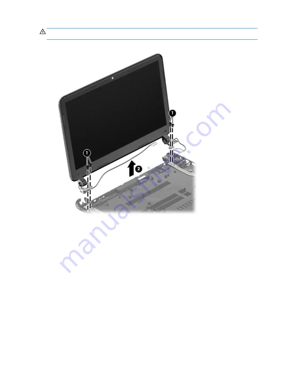
CAUTION:

Support the display assembly when removing the following screws. Failure to support

the display assembly can result in damage to the display assembly and other computer components.

1.

Remove the four Phillips screws from the display hinges 

(1)

 and lift the display assembly 

(2)

.

2.

If it is necessary to replace the webcam/microphone module:

a.

Detach and release the webcam/microphone module as far as the webcam/microphone
module cable allows. (The webcam/microphone module is attached to the back cover with
double-sided tape.)

b.

Disconnect the webcam/microphone cable 

(1)

 from the webcam/microphone module.

72

Chapter 4   Removal and replacement procedures

Содержание Pavilion Sleekbook 14

Страница 1: ...HP Pavilion 14 Sleekbook and HP Pavilion 14 Ultrabook Maintenance and Service Guide ...

Страница 2: ...nd Windows are U S registered trademarks of Microsoft Corporation SD Logo is a trademark of its proprietor The information contained herein is subject to change without notice The only warranties for HP products and services are set forth in the express warranty statements accompanying such products and services Nothing herein should be construed as constituting an additional warranty HP shall not...

Страница 3: ...w another hard surface such as an adjoining optional printer or a soft surface such as pillows or rugs or clothing to block airflow Also do not allow the AC adapter to contact the skin or a soft surface such as pillows or rugs or clothing during operation The device and the AC adapter comply with the user accessible surface temperature limits defined by the International Standard for Safety of Inf...

Страница 4: ...iv Safety warning notice ...

Страница 5: ...embly subcomponents 22 Miscellaneous parts 23 Sequential part number listing 23 4 Removal and replacement procedures 28 Preliminary replacement requirements 28 Tools required 28 Service considerations 28 Plastic parts 28 Cables and connectors 28 Drive handling 29 Grounding guidelines 29 Electrostatic discharge damage 29 Packaging and transporting guidelines 31 Component replacement procedures 32 S...

Страница 6: ...the BIOS version 76 Downloading a BIOS update 77 Using System Diagnostics 78 6 Ubuntu Linux Using Setup Utility BIOS and System Diagnostics 79 Starting Setup Utility 79 Using Setup Utility 79 Changing the language of Setup Utility 79 Navigating and selecting in Setup Utility 79 Displaying system information 80 Restoring factory default settings in Setup Utility 80 Exiting Setup Utility 80 Updating...

Страница 7: ... Recovery partition to recover a minimized image 89 Using HP Recovery media to recover 90 Changing the computer boot order 90 Removing the HP Recovery partition 90 9 Ubuntu Linux Backing up restoring and recovering 91 Performing a system recovery 91 Creating the restore DVDs 91 Creating a restore image on a USB device 91 Performing recovery using the restore media 92 Backing up your information 92...

Страница 8: ...viii ...

Страница 9: ...eration Intel Core i3 processors Intel Core i3 3227U 1 9 GHz 1600 MHz 3 MB L3 cache dual core 17 W Intel Core i3 3217U 1 8 GHz 1600 MHz 3 MB L3 cache dual core 17 W 2nd Generation Intel Core i3 processors Intel Core i3 2377M 1 5 GHz 1066 MHz 3 MB L3 cache dual core 17 W Intel Core i3 2375M 1 5 GHz 1066 MHz 3 MB L3 cache dual core 17 W AMD processors AMD A6 4455M 2 6 GHz 2 1 GHz 1 MB L2 cache 1333 ...

Страница 10: ...ors Intel HD Graphics 3000 for use with computer models with 2nd Generation Intel Core processors Internal graphics UMA for use with computer models with AMD processors AMD Radeon HD 7500 graphics for use with computer models with AMD A6 4475M processors AMD Radeon HD 7400G graphics for use with computer models with AMD A4 4375M processors AMD Radeon HD 7340 graphics for use with computer models w...

Страница 11: ... DDR3L 1600 MHz Dual Channel support for use with computer models with 3rd Generation Intel Core processors DDR3 1333 MHz support DDR3 1600 DDR3L 1600 downgrade to DDR3 1333 for use with computer models with 2nd Generation Intel Core processors or AMD E2 2000 AMD E2 1800 AMD A6 4455 or AMD A4 4355M processors DDR3 1066 MHz support DDR3 1600 downgraded to DDR3 1066 for use with computer models with...

Страница 12: ...5400 rpm 9 5 mm 640 GB 5400 rpm 9 5 mm 500 GB 7200 rpm 9 5 mm 500 GB 5400 rpm 9 5 mm 500 GB 5400 rpm 7 0 mm 320 GB 5400 rpm 9 5 mm 320 GB 5400 rpm 7 0 mm Supports 32 GB mSATA solid state drive for use with computer models with Intel Core processors with system memory up to 8 GB not supported on Ubuntu Linux Supports 24 GB mSATA solid state drive for use with computer models with Intel Core process...

Страница 13: ...and Bluetooth 4 0 Combination Adapter not supported on Ubuntu Linux select models only Ralink RT3290LE 802 11 b g n 1x1 WiFi and Bluetooth 4 0 Combination Adapter select models only Ralink RT5390R 802 11 b g n 1 1 WiFi select models only External media card HP Multi Format Digital Media Reader slot with push push technology supporting the following digital card formats Secure Digital SD Memory Car...

Страница 14: ...chPad with two buttons Multitouch gesture support enabled as default Taps enabled by default Supports edge swipe gestures Power requirements AC adapter 65 W RC V AC adapter with localized cable plug support 3 wire plug with ground pin supports 3 pin DC connector Battery 4 cell 37 Whr 2 55 Ah Li ion battery Supports fast charge Security Security cable slot Intel AT p Ready support Operating system ...

Страница 15: ... video captures still photographs and allows you to video conference and chat online using streaming video 4 Internal microphone Records sound The antennas are not visible from the outside of the computer For optimal transmission keep the areas immediately around the antennas free from obstructions For wireless regulatory notices see the section of the Regulatory Safety and Environmental Notices t...

Страница 16: ...ntu Linux Turns the TouchPad on or off 3 TouchPad zone Moves the on screen pointer and selects or activates items on the screen NOTE The TouchPad also supports edge swipe gestures 4 Left TouchPad button Functions like the left button on an external mouse 5 Right TouchPad button Functions like the right button on an external mouse 8 Chapter 2 External component identification ...

Страница 17: ...an energy saving mode that uses the least amount of power 2 Caps lock light White Caps lock is on which switches the letter keys to all capital letters 3 Mute light Amber Computer sound is off Off Computer sound is on 4 Wireless light White An integrated wireless device such as a wireless local area network WLAN device and or a Bluetooth device is on Amber All wireless devices are off 5 TouchPad l...

Страница 18: ...CAUTION Pressing and holding down the power button will result in the loss of unsaved information If the computer has stopped responding and shutdown procedures are ineffective press and hold the power button down for at least 5 seconds to turn off the computer NOTE For select models the Intel Rapid Start Technology feature is enabled at the factory Rapid Start Technology allows your computer to r...

Страница 19: ...key for Windows computer models 3 Operating system key For Windows computer models returns you to the Start screen from an open app or the Desktop NOTE Pressing the operating system logo key again will return you to the previous screen For Linux computer models displays the operating system menu 4 Action keys Execute frequently used system functions 5 Applications key Displays options for a select...

Страница 20: ...Audio out headphone jack audio in microphone jack Produces sound when connected to optional powered stereo speakers headphones earbuds a headset or television audio Also connects an optional headset microphone The jack does not support optional microphone only devices WARNING To reduce the risk of personal injury adjust the volume before using headphones earbuds or a headset For additional safety ...

Страница 21: ...ing accessed Amber HP 3D DriveGuard has temporarily parked the hard drive select models only 3 Digital Media Slot Supports the following digital card formats Secure Digital SD Memory Card Secure Digital High Capacity SDHC Memory Card Secure Digital Extended Capacity SDxC Memory Card MultiMediaCard MMC 4 USB 3 0 ports 2 Connect optional USB 3 0 devices and provide enhanced USB power performance 5 H...

Страница 22: ...ed and the battery is charged Blinking white The battery has reached a low battery level Amber The AC adapter is connected and the battery is charging Off The computer is using DC power 9 Power connector Connects an AC adapter 14 Chapter 2 External component identification ...

Страница 23: ... 3 Vents 4 Enable airflow to cool internal components NOTE The computer fan starts up automatically to cool internal components and prevent overheating It is normal for the internal fan to cycle on and off during routine operation 4 Battery release latch Releases the battery from the battery bay Bottom 15 ...

Страница 24: ...el name for the computer 2 Serial number This is an alphanumeric identifier that is unique to each product 3 Product part number This number provides specific information about the product s hardware components The part number helps a service technician to determine what components and parts are needed 4 Warranty period This number describes the duration of the warranty period for the computer 5 M...

Страница 25: ...LED SVA BrightView flat display assembly The display assembly is spared at the subcomponent level only NOTE For a full list of display spare parts see Display assembly subcomponents on page 22 2 Keyboard black finish includes keyboard cable For use in Canada 697904 DB1 Computer major components 17 ...

Страница 26: ...81 For use in Turkey for use with computer models with Intel processors 697904 141 For use in the United Kingdom for use with computer models with Intel processors 697904 031 For use in the United States 697904 001 3 Top cover includes TouchPad Ruby red 697920 001 Silver 704382 001 Sparkling black 698488 001 4 Power button board includes cable 697901 001 5 System board includes processor and repla...

Страница 27: ...with Intel HM77 chipsets and i5 3317U processors For Windows 8 Standard 698491 501 For Ubuntu Linux or FreeDOS 1 0 698491 001 For use with computer models with Intel HM77 chipsets and i3 3227U processors For Windows 8 Standard 718726 501 For Ubuntu Linux or FreeDOS 1 0 718726 001 For use with computer models with Intel HM77 chipsets and i3 3217U processors For Windows 8 Standard 698492 501 For Ubu...

Страница 28: ...12800 4 GB 641369 005 2 GB 652972 005 7 Heat sink includes replacement thermal material Heat sink for computer models with switchable discrete graphics 697916 001 Heat sink for computer models with UMA graphics not illustrated 697915 001 8 mSATA solid state drive 32 GB for computer models with Intel Core processors not supported on Ubuntu Linux 698524 001 mSATA solid state drive 24 GB for use with...

Страница 29: ...x select models only 690019 005 Ralink RT3290LE 802 11 b g n 1x1 WiFi and Bluetooth 4 0 Combination Adapter select models only 690020 005 Ralink RT5390R 802 11 b g n 1 1 WiFi select models only 691415 005 12 Platform Controller Hub PCH heat sink 699248 001 13 Speaker assembly includes left and right speakers and cable 697918 001 14 Battery 4 cell 37 Whr 2 55 Ah 695192 001 15 Fan 697914 001 16 RJ 4...

Страница 30: ... WLED SVA BrightView flat display panel 698523 001 4 Webcam microphone module 697903 001 5 Antenna Kit includes left and right wireless antenna cables and transceivers 697913 001 6 Display Panel Cable Kit includes display panel cable and webcam microphone module cable 697911 001 7 Back cover Ruby red 697909 001 Silver 704381 001 Sparkling black 697910 001 22 Chapter 3 Illustrated parts catalog ...

Страница 31: ... optical drive not illustrated DVD RW Super Multi Double Layer Combination Drive 659940 001 Screw Kit not illustrated 697912 001 Thermal Material Kit 680571 001 Sequential part number listing Spare part number Description 490371 001 Power cord for use in North America black 3 pin 1 83 m 490371 011 Power cord for use in Australia black 3 pin 1 83 m 490371 021 Power cord for use in Europe black 3 pi...

Страница 32: ...69300 005 640 GB 5400 rpm hard drive 9 5 mm 0 37 in 6 35 cm 2 50 in SATA does not include hard drive bracket or cable 670290 005 Intel Centrino Wireless N 2230 802 11 b g n 2 2 WiFi and Bluetooth 4 0 combination adapter for use with computer models with Intel processors 675794 005 Qualcomm Atheros AR9485 802 11 b g n 1 1 WiFi Adapter 676521 005 1 TB 5400 rpm hard drive 9 5 mm 0 37 in 6 35 cm 2 50 ...

Страница 33: ...e in Taiwan includes cable 697904 AD1 Keyboard with black finish for use in South Korea includes cable 697904 B31 Keyboard with black finish for use internationally includes cable for use with computer models with Intel processors only 697904 BB1 Keyboard with black finish for use in Israel includes cable for use with computer models with Intel processors only 697904 DB1 Keyboard with black finish...

Страница 34: ...524 001 mSATA solid state drive 32 GB for use with computer models with Intel Core processors not supported on Ubuntu Linux 699248 001 PCH heat sink 699811 001 System board for use with computer models with UMA video memory AMD A68M chipsets E1 1200 processors and Ubuntu Linux or FreeDOS 2 0 699811 501 System board for use with computer models with UMA video memory AMD A68M chipsets E1 1200 proces...

Страница 35: ...tandard 718727 001 System board for use with computer models with switchable discrete graphics Intel HM77 chipsets I5 3337U processors 1 GB of dedicated video memory and FreeDOS 1 0 718727 501 System board for use with computer models with switchable discrete graphics Intel HM77 chipsets I5 3337U processors 1 GB of dedicated video memory and Windows 8 Standard 718728 001 System board for use with ...

Страница 36: ...sembly can damage plastic parts Use care when handling the plastic parts Apply pressure only at the points designated in the maintenance instructions Cables and connectors CAUTION When servicing the computer be sure that cables are placed in their proper locations during the reassembly process Improper cable placement can damage the computer Cables must be handled with extreme care to avoid damage...

Страница 37: ... Electronic components are sensitive to electrostatic discharge ESD Circuitry design and structure determine the degree of sensitivity Networks built into many integrated circuits provide some protection but in many cases ESD contains enough power to alter device parameters or melt silicon junctions A discharge of static electricity from a finger or other conductor can destroy static sensitive dev...

Страница 38: ... V Motions of bench worker 6 000 V 800 V 400 V Removing DIPS from plastic tube 2 000 V 700 V 400 V Removing DIPS from vinyl tray 11 500 V 4 000 V 2 000 V Removing DIPS from Styrofoam 14 500 V 5 000 V 3 500 V Removing bubble pack from PCB 26 500 V 20 000 V 7 000 V Packing PCBs in foam lined box 21 000 V 11 000 V 5 000 V 30 Chapter 4 Removal and replacement procedures ...

Страница 39: ...nd and that proper materials are selected to avoid static charging When grounding is not possible use an ionizer to dissipate electric charges Workstation guidelines Follow these grounding workstation guidelines Cover the workstation with approved static shielding material Use a wrist strap connected to a properly grounded work surface and use properly grounded tools and equipment Use conductive f...

Страница 40: ...ended to prevent electrostatic damage Antistatic tape Antistatic smocks aprons and sleeve protectors Conductive bins and other assembly or soldering aids Nonconductive foam Conductive tabletop workstations with ground cords of one megohm resistance Static dissipative tables or floor mats with hard ties to the ground Field service kits Static awareness labels Material handling packages Nonconductiv...

Страница 41: ...the computer 2 Serial number This is an alphanumeric identifier that is unique to each product 3 Product part number This number provides specific information about the product s hardware components The part number helps a service technician to determine what components and parts are needed 4 Warranty period This number describes the duration of the warranty period for the computer 5 Model descrip...

Страница 42: ...e computer Remove the battery 1 Turn the computer upside down on a flat surface 2 Slide the battery release lock 1 far enough that it rests in the unlocked position 3 Slide the battery release latch 2 to release the battery 4 Slide the battery 3 from the middle to remove it from the computer To insert the battery follow these steps CAUTION Do not slant the battery as you insert it 1 Holding the ba...

Страница 43: ...tion Computer feet Description Spare part number Rubber Feet Kit 697906 001 The computer feet are adhesive backed rubber pads There are 5 rubber feet that attach to the base enclosure in the locations illustrated below Component replacement procedures 35 ...

Страница 44: ...computer by first unplugging the power cord from the AC outlet and then unplugging the AC adapter from the computer 4 Remove the battery see Battery on page 34 NOTE To replace the entire display assembly additional steps are required see Display assembly on page 70 Remove the panel 1 Remove the plastic screw covers 1 and the two Phillips screws 2 that secure the display bezel to the display assemb...

Страница 45: ...for the display panel NOTE Support the display panel as you lean the panel forward 5 Move the panel toward the keyboard 1 6 Release the adhesive support strip 2 that secures the display panel cable connector to the display panel Component replacement procedures 37 ...

Страница 46: ...h computer models with Intel processors 697904 B31 For use in Israel for use with computer models with Intel processors 697904 BB1 For use in Japan 697904 291 For use in Latin America 697904 161 For use in Nordic countries for use with computer models with Intel processors 697904 DH1 For use in Portugal for use with computer models with Intel processors 697904 131 For use in Saudi Arabia for use w...

Страница 47: ...ize and location during removal and replacement Before removing the keyboard follow these steps 1 Shut down the computer 2 Disconnect all external devices connected to the computer 3 Disconnect the power from the computer by first unplugging the power cord from the AC outlet and then unplugging the AC adapter from the computer 4 Remove the battery see Battery on page 34 Remove the keyboard 1 Remov...

Страница 48: ...de Insert a thin tool through the keyboard access hole The keyboard icon indicates the keyboard access hole Push firmly on the bottom of the keyboard until it disengages from the computer 3 Turn the computer right side up with the front toward you and open the display 40 Chapter 4 Removal and replacement procedures ...

Страница 49: ...Lift up on the rear of the keyboard 5 Tilt the keyboard forward 1 onto the palm rest Release the zero insertion force ZIF connector 2 to which the keyboard cable is attached and then disconnect the keyboard cable 3 from the system board 6 Remove the keyboard Component replacement procedures 41 ...

Страница 50: ...crew and screw lock size and location during removal and replacement Before removing the top cover follow these steps 1 Shut down the computer 2 Disconnect all external devices connected to the computer 3 Disconnect the power from the computer by first unplugging the power cord from the AC outlet and then unplugging the AC adapter from the computer 4 Remove the battery see Battery on page 34 5 Rem...

Страница 51: ...ve the seven Phillips screws that secure the top cover to the base enclosure 2 Disconnect the power button cable 1 and the TouchPad cable 2 3 Close the display and turn the computer upside down Component replacement procedures 43 ...

Страница 52: ...tly lift around the edges of the top cover 1 and lift to remove the top cover 2 When replacing the top cover be sure that the power button board and cable see Power button board on page 45 are removed from the defective top cover and installed on the replacement top cover 44 Chapter 4 Removal and replacement procedures ...

Страница 53: ...ing the power cord from the AC outlet and then unplugging the AC adapter from the computer 4 Remove the battery see Battery on page 34 5 Remove the keyboard see Keyboard on page 38 6 Remove the top cover see Top cover on page 42 Remove the power button board 1 Turn the top cover upside down with the front toward you 2 Remove the Phillips screw 1 and tape that secure the power button board to the t...

Страница 54: ... Drive Hardware Kit includes hard drive cable and hard drive bracket and screws 697905 001 IMPORTANT Make special note of each screw and screw lock size and location during removal and replacement Before removing the hard drive follow these steps 1 Shut down the computer 2 Disconnect all external devices connected to the computer 3 Disconnect the power from the computer by first unplugging the pow...

Страница 55: ...f the hard drive from the computer NOTE If it is necessary to replace the hard drive cable see System board on page 53 2 Remove the two Phillips screws 1 Lift the hard drive 2 to remove and disconnect the hard drive cable 3 Component replacement procedures 47 ...

Страница 56: ...3 Remove the four Phillips screws 1 and then remove the bracket 2 from the hard drive To install a hard drive reverse the removal procedure 48 Chapter 4 Removal and replacement procedures ...

Страница 57: ...t unplugging the power cord from the AC outlet and then unplugging the AC adapter from the computer 4 Remove the battery see Battery on page 34 5 Remove the keyboard see Keyboard on page 38 6 Remove the top cover see Top cover on page 42 7 Remove the hard drive see Hard drive on page 46 Remove the USB board NOTE One side of the USB cable lies across the hard drive It is disconnected during the har...

Страница 58: ... lock size and location during removal and replacement CAUTION To prevent an unresponsive system replace the wireless module only with a wireless module authorized for use in the computer by the governmental agency that regulates wireless devices in your country or region If you replace the module and then receive a warning message remove the module to restore device functionality and then contact...

Страница 59: ...NOTE The 1 black WLAN antenna cable is connected to the WLAN module 1 Main terminal The 2 white WLAN antenna cable is connected to the WLAN module 2 Aux terminal 2 Remove the Phillips screw 2 that secures the WLAN module to the system board The WLAN module tilts up Component replacement procedures 51 ...

Страница 60: ... incorrect installation into the WLAN module socket NOTE If the WLAN antennas are not connected to the terminals on the WLAN module the protective sleeves should be installed on the antenna connectors as shown in the following illustration Reverse this procedure to install the WLAN module 52 Chapter 4 Removal and replacement procedures ...

Страница 61: ...mputer models with Intel HM77 chipsets i3 3227U processors and 1 GB of dedicated video memory For Windows 8 Standard 718728 501 For FreeDOS 1 0 718728 001 For use with computer models with Intel HM77 chipsets i3 2377M processors and 1 GB of dedicated video memory For Windows 8 Standard 698495 501 For FreeDOS 1 0 698495 001 For use with computer models with Intel HM77 chipsets i3 2375M processors a...

Страница 62: ... A68M chipsets and E2 2000 processors For Windows 8 Standard 703856 501 For Ubuntu Linux or FreeDOS 2 0 703856 001 For use with computer models with AMD A68M chipsets and E2 1800 processors For Windows 8 Standard 699812 501 For Ubuntu Linux or FreeDOS 2 0 699812 001 For use with computer models with AMD A68M chipsets and E1 1500 processors For Windows 8 Standard 703855 501 For Ubuntu Linux or Free...

Страница 63: ...lled on the replacement system board Memory module see Memory module on page 58 RTC battery see RTC battery on page 61 Heat sink see Heat sink on page 65 PCH heat sink see PCH heat sink on page 64 mSATA solid state drive see mSATA solid state drive on page 62 Remove the system board NOTE The heat sink on your system board may appear different from the heat sink shown 1 Disconnect the following cab...

Страница 64: ...de of the system board 1 until it rests at an angle 5 Remove the system board by sliding it up and to the left at an angle 2 6 Disconnect the power connector cable 3 7 Remove the hard drive cable a Turn the system board upside down with the front toward you 56 Chapter 4 Removal and replacement procedures ...

Страница 65: ...b Disconnect the hard drive cable from the system board Reverse this procedure to install the system board Component replacement procedures 57 ...

Страница 66: ...wn the computer 2 Disconnect all external devices connected to the computer 3 Disconnect the power from the computer by first unplugging the power cord from the AC outlet and then unplugging the AC adapter from the computer 4 Remove the battery see Battery on page 34 5 Remove the keyboard see Keyboard on page 38 6 Remove the top cover see Top cover on page 42 7 Remove the hard drive see Hard drive...

Страница 67: ...he components on the memory module CAUTION To protect a memory module after removal place it in an electrostatic safe container To replace the memory module 1 Align the notched edge of the replacement memory module with the tab in the memory module slot and then press the module 1 into the slot at a 45 degree angle until it is firmly seated Component replacement procedures 59 ...

Страница 68: ...l the side retention clips snap back into place 3 Reverse the previous removal steps to replace the following items System board WLAN USB board Hard drive Top cover Keyboard Battery Any external devices and the AC adapter 60 Chapter 4 Removal and replacement procedures ...

Страница 69: ... battery see Battery on page 34 5 Remove the keyboard see Keyboard on page 38 6 Remove the top cover see Top cover on page 42 7 Remove the hard drive see Hard drive on page 46 8 Remove the USB board see USB board audio jack on page 49 9 Remove the WLAN see WLAN module on page 50 10 Remove the system board see System board on page 53 Remove the RTC battery 1 Turn the system board upside down with t...

Страница 70: ... Disconnect all external devices connected to the computer 3 Disconnect the power from the computer by first unplugging the power cord from the AC outlet and then unplugging the AC adapter from the computer 4 Remove the battery see Battery on page 34 5 Remove the keyboard see Keyboard on page 38 6 Remove the top cover see Top cover on page 42 7 Remove the hard drive see Hard drive on page 46 8 Rem...

Страница 71: ...d state drive 2 NOTE The drive tilts up to remove The drive is designed with a notch to prevent incorrect installation into mSATA drive socket Reverse this procedure to install the mSATA drive onto a replacement system board Component replacement procedures 63 ...

Страница 72: ...m the computer 4 Remove the battery see Battery on page 34 5 Remove the keyboard see Keyboard on page 38 6 Remove the top cover see Top cover on page 42 7 Remove the hard drive see Hard drive on page 46 8 Remove the USB board see USB board audio jack on page 49 9 Remove the WLAN see WLAN module on page 50 10 Remove the system board see System board on page 53 Remove the PCH heat sink 1 Turn the sy...

Страница 73: ...t and then unplugging the AC adapter from the computer 4 Remove the battery see Battery on page 34 5 Remove the keyboard see Keyboard on page 38 6 Remove the top cover see Top cover on page 42 7 Remove the hard drive see Hard drive on page 46 8 Remove the USB board see USB board audio jack on page 49 9 Remove the WLAN see WLAN module on page 50 10 Remove the system board see System board on page 5...

Страница 74: ...s heat sink 3 from the system board CAUTION To prevent damage to the cooling tubes do not lift the assembly by the cooling tubes The tubes bend easily b Thoroughly clean the thermal connections 1 and 3 on the system board and the heat sink 2 and 4 before replacing a heat sink onto a system board Continue to step 3 66 Chapter 4 Removal and replacement procedures ...

Страница 75: ...se this procedure to replace the heat sink Replace the thermal material that ships with the replacement heat sink Fan Description Spare part number Fan 697914 001 IMPORTANT Make special note of each screw and screw lock size and location during removal and replacement Before removing the fan follow these steps 1 Shut down the computer 2 Disconnect all external devices connected to the computer Com...

Страница 76: ... the base enclosure 1 Disconnect the fan cable 2 Remove the three Phillips screws 1 from the fan 2 and lift up to remove the fan Reverse this procedure to install the cooling fan in the base enclosure Speaker assembly Description Spare part number Speaker assembly 697918 001 IMPORTANT Make special note of each screw and screw lock size and location during removal and replacement Before removing th...

Страница 77: ...ews were removed during the process to remove the top cover 1 Gently release the wires 1 routed along the top of the base enclosure 2 Lift both pieces of the speaker assembly 2 Reverse this procedure to install the speaker assembly on the base enclosure RJ 45 cover Description Spare part number RJ 45 cover 700428 001 IMPORTANT Make special note of each screw and screw lock size and location during...

Страница 78: ...board on page 53 Remove the RJ 45 cover 1 Remove the Phillips M screw 1 for the RJ 45 cover 2 Lift the RJ 45 cover 2 to remove it from the base enclosure Reverse these procedures to replace the RJ 45 cover Display assembly Description Spare part number Antenna Kit includes left and right wireless antenna cables and transceivers 697913 001 Display Panel Cable Kit includes display panel cable and we...

Страница 79: ...e AC outlet and then unplugging the AC adapter from the computer 4 Remove the battery see Battery on page 34 5 Remove the display panel see Display panel on page 36 6 Remove the keyboard see Keyboard on page 38 7 Remove the top cover see Top cover on page 42 8 Remove the hard drive see Hard drive on page 46 9 Remove the USB board see USB board audio jack on page 49 10 Remove the WLAN see WLAN modu...

Страница 80: ...om the display hinges 1 and lift the display assembly 2 2 If it is necessary to replace the webcam microphone module a Detach and release the webcam microphone module as far as the webcam microphone module cable allows The webcam microphone module is attached to the back cover with double sided tape b Disconnect the webcam microphone cable 1 from the webcam microphone module 72 Chapter 4 Removal a...

Страница 81: ...two top screws 1 and two bottom screws 2 from the display bracket and lift the display brackets 3 to remove them 4 If it is necessary to replace the display panel cable a Gently remove the cable from the routing clips 1 Component replacement procedures 73 ...

Страница 82: ... the wireless antenna cables from the clips 1 built into the back cover b Release the wireless antenna transceivers from the back cover The wireless antenna transceivers are attached to the back cover with double sided tape c Remove the wireless antenna cables and transceivers 2 Reverse this procedure to reassemble and install the display assembly 74 Chapter 4 Removal and replacement procedures ...

Страница 83: ... battery see Battery on page 34 5 Remove the keyboard see Keyboard on page 38 6 Remove the top cover see Top cover on page 42 7 Remove the hard drive see Hard drive on page 46 8 Remove the USB board see USB board audio jack on page 49 9 Remove the WLAN see WLAN module on page 50 10 Remove the system board see System board on page 53 11 Remove the display assembly see Display panel on page 36 Remov...

Страница 84: ... the BIOS Updated versions of the BIOS may be available on the HP website Most BIOS updates on the HP website are packaged in compressed files called SoftPaqs Some download packages contain a file named Readme txt which contains information regarding installing and troubleshooting the file Determining the BIOS version To determine whether available BIOS updates contain later BIOS versions than tho...

Страница 85: ...er identifier You may need this information to locate the update later after it has been downloaded to your hard drive b Follow the on screen instructions to download your selection to the hard drive Make a note of the path to the location on your hard drive where the BIOS update is downloaded You will need to access this path when you are ready to install the update NOTE If you connect your compu...

Страница 86: ...operly To start System Diagnostics 1 Turn on or restart the computer quickly press esc and then press f2 2 Click the diagnostic test you want to run and then follow the on screen instructions NOTE If you need to stop a diagnostic test while it is running press esc 78 Chapter 5 Windows 8 Using Setup Utility BIOS and System Diagnostics ...

Страница 87: ...art Setup Utility 2 Use the arrow keys to select System Configuration Language and then press enter 3 Use the arrow keys to select a language and then press enter 4 When a confirmation prompt with your language selected is displayed press enter 5 To save your change and exit Setup Utility use the arrow keys to select Exit Exit Saving Changes and then press enter Your change takes effect immediatel...

Страница 88: ...elect Exit Exit Saving Changes and then press enter The Setup Utility factory settings take effect when the computer restarts NOTE Your password security and language settings are not changed when you restore the factory settings Exiting Setup Utility To exit Setup Utility and save your changes from the current session If the Setup Utility menus are not visible press esc to return to the menu disp...

Страница 89: ...ning on battery power or connected to an optional power source During the download and installation follow these instructions Do not disconnect power from the computer by unplugging the power cord from the AC outlet Do not shut down the computer or initiate Suspend or Hibernation Do not insert remove connect or disconnect any device cable or cord 1 Access the page on the HP website that provides s...

Страница 90: ...es If it reports an error replace the memory modules immediately Battery test This test analyzes the condition of the battery and calibrates the battery if necessary If the battery fails the test contact support to report the issue and purchase a replacement battery System Tune Up This group of additional tests checks your computer to make sure that the main components are functioning correctly Sy...

Страница 91: ... to 90 Nonoperating 5 to 95 Maximum altitude unpressurized Operating 14 7 to 10 1 psia 15 m to 3 048 m 50 ft to 10 000 ft Nonoperating 14 7 to 4 4 psia 15 m to 12 192 m 50 ft to 40 000 ft Shock Operating 125 g 2 ms half sine Nonoperating 200 g 2 ms half sine Random vibration Operating 0 75 g zero to peak 10 Hz to 500 Hz 0 25 oct min sweep rate Nonoperating 1 50 g zero to peak 10 Hz to 500 Hz 0 5 o...

Страница 92: ...TA SATA SATA Transfer rate 300 MB sec 300 MB sec 300 MB sec 300 MB sec 300 MB sec Security ATA security ATA security ATA security ATA security ATA security Seek times typical read including setting Single track 1 5 ms 1 0 ms 1 0 ms 1 5 ms 2 0 ms Average 11 0 ms 14 0 ms 14 0 ms 12 0 ms 12 0 ms Maximum 22 0 ms 24 0 ms 22 0 ms 22 0 ms 22 0 ms Logical blocks 1 953 525 168 1 465 128 359 1 250 242 867 9...

Страница 93: ...oftware but not other software applications Factory Reset Restores the computer to the state its original factory state by deleting all information from the hard drive and re creating the partitions Then it reinstalls the operating system and the software that was installed at the factory See Creating HP Recovery media on page 86 2 As you add hardware and software programs create system restore po...

Страница 94: ...DVD RW or BD RE rewritable Blu ray discs they are not compatible with HP Recovery Manager software Or instead you can use a high quality blank USB flash drive If your computer does not include an integrated optical drive with DVD writer capability but you would like to create DVD recovery media you can use an external optical drive purchased separately to create recovery discs or you can obtain re...

Страница 95: ...ing your personal information settings or apps that came preinstalled on your computer or were purchased from the Windows Store consider using Windows Refresh This option does not require backing up data to another drive See Using Windows Refresh for quick and easy recovery on page 88 If you want to reset your computer to its original state Windows provides an easy way to remove all personal data ...

Страница 96: ...creen and then select General from the PC settings screen 4 Under Refresh your PC without affecting your files select Get started and follow the on screen instructions Remove everything and reinstall Windows Sometimes you want to perform detailed reformatting of your computer or you want to remove personal information before you give away or recycle your computer The process described in this sect...

Страница 97: ... with this computer you must either download the software from the manufacturer s website or reinstall the software from the media provided by the manufacturer Recovery through HP Recovery Manager should be used as a final attempt to correct computer issues HP Recovery media must be used if the computer hard drive fails To use the Factory Reset or System Recovery options you must use HP Recovery m...

Страница 98: ...p information You can change the selection for an optical drive or a USB flash drive To change the boot order 1 Insert the HP Recovery media you created 2 Restart the computer 3 Press and hold esc while the computer is restarting and then press f9 for boot options 4 Select the optical drive or USB flash drive you want to boot from 5 Follow the on screen instructions Removing the HP Recovery partit...

Страница 99: ...tes a set of system restore discs using blank writable DVDs DVD R or DVD R HP recommends using blank DVD R discs from a manufacturer you trust because these recovery DVDs are so important You need approximately 3 blank DVD R discs The program states how many discs are needed at the beginning of the process To create restore DVDs 1 Click the System menu icon at the far right of the top panel and th...

Страница 100: ...een instructions NOTE If you are unable to boot start up your computer with the primary operating system and you did not create a system recovery disc you must purchase an Ubuntu Operating System DVD to reinstall the operating system For additional information refer to the Worldwide Telephone Numbers booklet for more information Backing up your information You should back up your computer files on...

Страница 101: ...icon at the far right of the top panel and then click System Settings Backup icon 2 Click Restore select the location of the backup files and the folder name and then click Forward 3 Under Restore from When select the date of the files to be restored and click Forward 4 Select the location and folder where the files are to be restored and click Forward 5 Follow the on line instructions 6 Click Res...

Страница 102: ...rements are applicable to all countries and regions The length of the power cord set must be at least 1 0 m 3 3 ft and no more than 2 0 m 6 5 ft All power cord sets must be approved by an acceptable accredited agency responsible for evaluation in the country or region where the power cord set will be used The power cord sets must have a minimum current capacity of 10 A and a nominal voltage rating...

Страница 103: ...ark DEMKO 1 Finland FIMKO 1 France UTE 1 Germany VDE 1 India ISI 1 Israel SII 1 Italy IMQ 1 Japan JIS 3 The Netherlands KEMA 1 New Zealand SANZ 1 Norway NEMKO 1 The People s Republic of China CCC 4 Saudi Arabia SASO 7 Singapore PSB 1 South Africa SABS 1 South Korea KTL 5 Sweden SEMKO 1 Switzerland SEV 1 Taiwan BSMI 6 Thailand TISI 1 The United Kingdom ASTA 1 Requirements for specific countries and...

Страница 104: ...nductor size The wall plug must be a two pole grounding type with a Japanese Industrial Standard C8303 7 A 125 V ac configuration 4 The flexible cord must be Type RVV 3 conductor 0 75 mm conductor size Power cord set fittings appliance coupler and wall plug must bear the CCC certification mark 5 The flexible cord must be Type H05VV F 3 conductor 0 75 mm conductor size KTL logo and individual appro...

Страница 105: ...general household waste Follow the local laws and regulations in your area for battery disposal HP encourages customers to recycle used electronic hardware HP original print cartridges and rechargeable batteries For more information about recycling programs see the HP website at www hp com recycle 97 ...

Страница 106: ...ging HP Recovery Manager for Windows 8 computer models 90 buttons left TouchPad 8 power 10 right TouchPad 8 TouchPad on off 8 C cables service considerations 28 caps lock light identifying 9 chipset product description 2 components bottom 15 display 7 left side 12 right side 13 top 8 computer feet locations 35 spare part number 21 25 35 computer major components 17 computer reset for Windows 8 com...

Страница 107: ...ption 5 internal microphone identifying 7 J jack audio in microphone 12 audio out headphone 12 network 13 RJ 45 network 13 RJ 45 network lights 13 K keyboard product description 6 removal 38 spare part numbers 17 18 24 25 38 keys action 11 applications 11 esc 11 fn 11 operating system 11 Windows 11 Windows applications 11 L latch battery release 15 lights AC adapter 14 caps lock 9 hard drive 13 mu...

Страница 108: ...computer models 86 creating using HP Recovery Manager for Windows 8 computer models 86 recovery partition for Windows 8 computer models 89 removing for Windows 8 computer models 90 recycle computer for Windows 8 computer models 87 88 recycling 97 refresh computer for Windows 8 computer models 87 for Windows 8 computer models 88 removal replacement preliminaries 28 procedures 32 remove everything a...

Страница 109: ... Kit spare part number 23 24 tools required 28 top cover removal 42 spare part numbers 18 26 27 42 TouchPad buttons 8 TouchPad light 8 9 TouchPad on off button 8 TouchPad zone identifying 8 transporting guidelines 31 U USB 2 0 ports identifying 12 USB 3 0 ports identifying 13 USB board removal 49 spare part number 21 24 49 V vents identifying 12 15 video product description 4 W webcam light identi...

Отзывы: