background image

MSM466-R Outdoor 802.11n
Access Point Quick Start
Guide

Abstract

The MSM466-R 802.11n dual-radio Access Point [J9715A
(Americas), J9716A (Worldwide), J9717A (Japan), J9718A
(Israel)] brings 450 Mbps per radio technology to outdoor
environments for outdoor coverage, point to point and point
to multipoint applications either autonomously or centrally
controlled by MSM Controllers. This document describes
how to install and initially configure the MSM466-R,
hereafter referred to as the AP. The latest documentation is
available at

www.hp.com/support/manuals

.

© Copyright 2015 Hewlett-Packard Development Company, L.P.

*5998-6833*

HP Part Number: 5998-6833
Published: January 2015
Edition: 1

Hardware overview

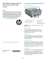
Figure 1 AP key components (bottom view)

1

1

2

1

6

5

3

4

4. Ethernet connector

1. Radio 2 antenna connectors (x3)

5. Reset button

2. Vent nut (do not remove)

6. Status LEDs (Power,

nl

Ethernet, Radio 1, Radio 2)

3. Grounding lug with screw

NOTE

: Three Radio 1 antenna connectors are on the

top of the AP.

Package contents

The AP, weatherproof RJ-45 Ethernet connector,
mounting bracket, 2 bracket bolts, 2 lock washers, 2
flat washers, 4 wall anchors and screws, 2 pole
clamps, and documentation.

Ethernet port

The Ethernet port is an auto-sensing 10/100/1000
Base-T (auto MDI/MDX) port with RJ-45 connector.
This port supports Power over Ethernet (PoE) 802.3af
and 802.3at (PoE+).

Antenna connectors

The AP includes no integrated antennas. It provides
three antenna connectors for each radio, color-coded
red, green, and blue. When connecting the antenna
cables, be sure to connect all three cables and to
respect the color-coding to ensure proper functionality.
See

“Available antennas” (page 10)

.

Reset button

The reset button is on the bottom of the AP, labeled as
5 on

Figure 1 (page 1)

. To reset the AP (same as

power cycling), press and release the reset button. To
reset the AP to factory defaults, press and hold the
reset button until the status LEDs flash three times, and
then release the button.

Page 1

Содержание MSM466-R

Страница 1: ...o 1 Radio 2 3 Grounding lug with screw NOTE Three Radio 1 antenna connectors are on the top of the AP Package contents The AP weatherproof RJ 45 Ethernet connector mounting bracket 2 bracket bolts 2 lock washers 2 flat washers 4 wall anchors and screws 2 pole clamps and documentation Ethernet port The Ethernet port is an auto sensing 10 100 1000 Base T auto MDI MDX port with RJ 45 connector This p...

Страница 2: ...its the available wireless channels ensuring compliant operation in the selected country Entering the incorrect country can result in illegal operation and can cause harmful interference to other systems Safety Consider the following safety information during installation If your network covers an area served by more than one power distribution system make sure all safety grounds are securely inte...

Страница 3: ...rom the screw nut 5 4 Thread the sealing nut 1 onto the left end of the clamp ring 3 Tighten it only enough to stay attached 5 Hold the screw nut 5 vertically with the open threads facing up and drop the body 6 into it with the RJ 45 connector opening facing up 6 Hold the clamp ring 3 vertically below the screw nut body items and screw the body 6 into the threads on the clamp ring 3 Tighten it onl...

Страница 4: ...s mounted on an outdoor wall The AP includes a built in Ethernet surge suppressor for its end of the Ethernet cable Mounting the AP The AP can be mounted on a pole or on a wall Pole installation IMPORTANT The AP and antennas can be mounted on a pole with a diameter of 32 to 57 mm 1 25 to 2 25 inches The pole must be capable of supporting the AP and antennas at the maximum anticipated wind loading ...

Страница 5: ... in position against the pole 5 and then fully tighten the pole clamp screw to anchor the AP against the pole 5 Attach the second pole clamp 4 in the same manner as the first also firmly tightening it 9 Rotate the AP body up or down to the wanted position and then tighten the bracket bolts to 50 kgf cm 43 4 lbf in Figure 6 AP mounted on pole 1 2 5 3 4 4 5 Pole 3 Pole clamp slot x4 1 Bracket post 4...

Страница 6: ... wanted position and then firmly tighten both bracket bolts to 50 kgf cm 43 4 lbf in Attaching the grounding wire and antennas 1 Remove the grounding screw shown in Figure 8 page 6 from the lug on the AP body Figure 8 Grounding cable 1 2 2 Grounding cable 1 Grounding screw 2 Attach a grounding cable 2 10 AWG or thicker with the grounding screw 3 Tighten the grounding screw and ensure that the cabl...

Страница 7: ...mation see Using autonomous mode page 8 Using controllers To become operational the AP must establish a management tunnel with a controller The controller manages the AP and provides all configuration settings When power is applied the AP establishes a connection to the controller automatically if default settings are used on the AP and the controller and both devices are on the same subnet No fur...

Страница 8: ...x MSM4xx APs Configuration Guide In autonomous mode the AP is managed via its web based management tool using Microsoft Internet Explorer 8 or later or Mozilla Firefox 9 0 1 or later Configuring your computer 1 Disconnect your computer LAN port and configure it as follows Set a static IP address in the range 192 168 1 2 to 192 168 1 254 Set a subnet mask of 255 255 255 0 Set the default gateway to...

Страница 9: ...ore information see Wireless protection in the MSM3xx MSM4xx APs Configuration Guide Assigning an IP address to the AP By default the AP operates as a DHCP client This means that if the network has a DHCP server the AP automatically receives a new IP address in place of its default address of 192 168 1 1 upon connecting to the network Use one of the following methods to assign an IP address to the...

Страница 10: ...ble indoor antennas are shown for the benefit of those who choose to install an AP in an indoor location NOTE For indoor installations indoor antennas can be used with the AP however RP SMA to standard N connector adapters not supplied are required to connect indoor antennas to the AP Elements Use Gain Band Type Part 3 Outdoor 6dBi 2 4 GHz Omni directional J9719A 3 Outdoor 8dBi 5 GHz Omni directio...

Страница 11: ...de with 2010 as the starting point and M is the month when the unit was manufactured For example 3A would indicate 3 for 2013 and A for the month of November Following this convention 2010 is indicated by 0 201 1 by 1 2012 by 2 2013 by 3 and so forth Months start at 1 for January 2 for February up to 9 for September 0 zero is used for October A for November and B for December Дата изготовления Дат...

Отзывы: