


Locate the SFP transceivers
77
D
SFP option for host ports
Locate the SFP transceivers
Locate the qualified SFP options for your MSA 2050 SAN controller module within your product ship kit. You can also
obtain the part numbers using the QuickSpecs.
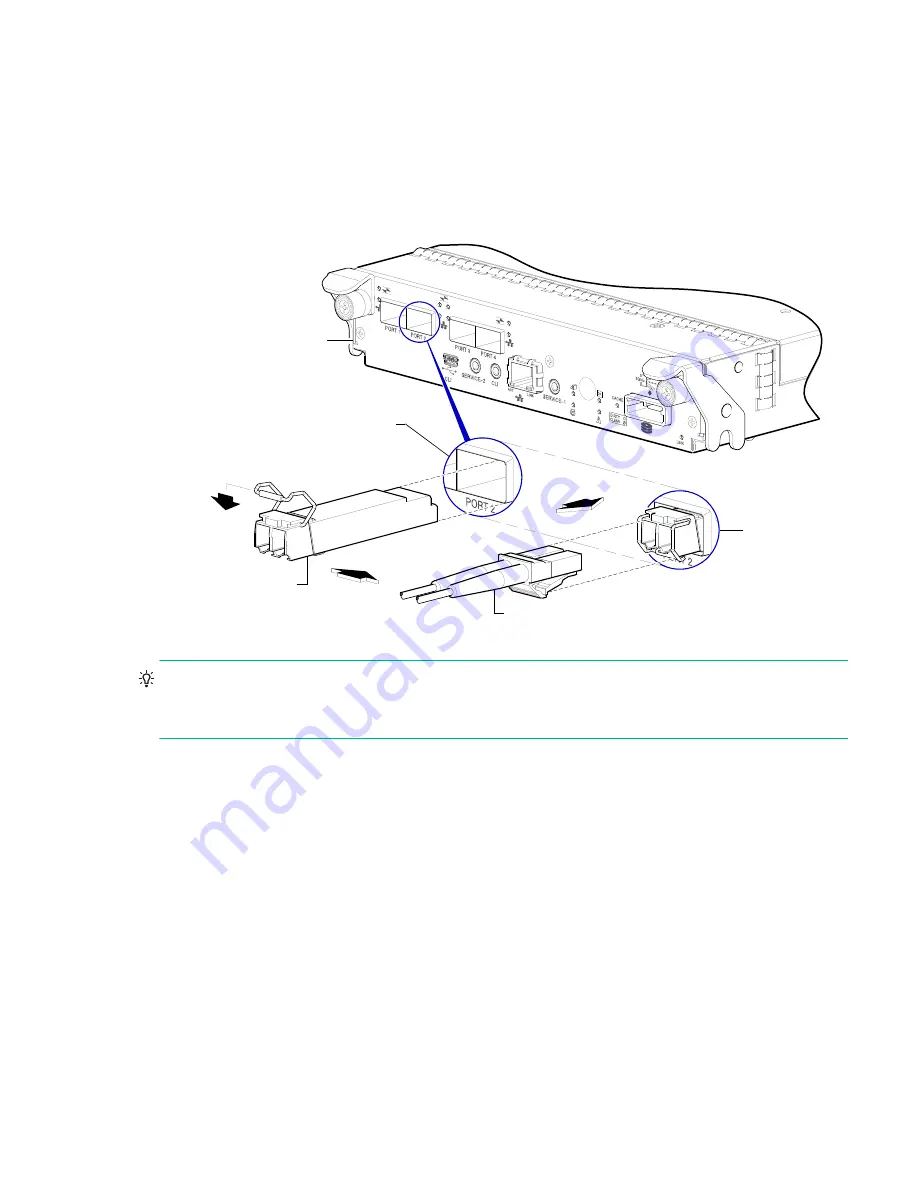
The SFP transceiver (SFP) should look similar to the generic SFP shown in the figure below. Follow the guidelines
provided in
“Electrostatic discharge” (page 76)
when installing an SFP.
Figure 36 Install a qualified SFP option
TIP:
See the “Configuring host ports” topic within the SMU Reference Guide for information about configuring
MSA 2050 SAN host ports with host interface protocols of the same type or a combination of types. Also see
CLI port and cable—known issues on Windows” (page 42)
.
Install an SFP transceiver
For each target MSA 2050 SAN host port, perform the following procedure to install an SFP. Refer to the figure above
when performing the steps.
1.
Orient the SFP as shown above, and align it for insertion into the target host port.
The SFP should be positioned such that the actuator pivot-hinge is on top.
2.
If the SFP has a plug, remove it before installing the transceiver. Retain the plug.
3.
Flip the actuator open as shown in the figure (near the left detail view).
The actuator on your SFP option may look slightly different than the one shown, and it may not open to a sweep
greater than 90
(as shown in the figure).
4.
Slide the SFP into the target host port until it locks into place.
5.
Flip the actuator down, as indicated by the down-arrow next to the open actuator in the figure.
The installed SFP should look similar to the position shown in the right detail view.
Installed SFP
(actuator closed)
Target host port
Align SFP for installation
(plug removed/actuator open)
Controller module face plate
Fibre-optic interface cable