background image

3

Illustrated parts catalog

Use this table to determine the spare parts that are available for the computer.

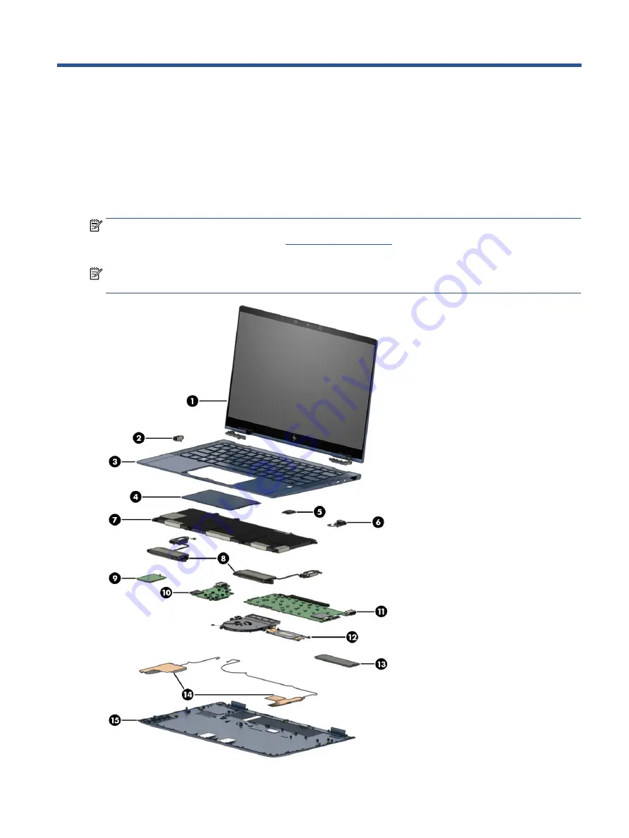
Computer major components

To identify the computer major components, use this illustration and table.

NOTE:

HP continually improves and changes product parts. For complete and current information about 

supported parts for your computer, go t

http://partsurfer.hp.com

, select your country or region, and then 

follow the on-screen instructions.

NOTE:

Details about your computer, including model, serial number, product key, and length of warranty, 

are on the service tag at the bottom of your computer.

Computer major components

17

Содержание Elite Dragonfly

Страница 1: ...Maintenance and Service Guide SUMMARY This guide provides information about spare parts removal and replacement of parts security backing up and more ...

Страница 2: ...nstrued as constituting an additional warranty HP shall not be liable for technical or editorial errors or omissions contained herein First Edition January 2021 Document Part Number M48358 001 Product notice This guide describes features that are common to most models Some features may not be available on your computer Not all features are available in all editions or versions of Windows Systems m...

Страница 3: ...ct the computer air vents Use the computer only on a hard flat surface Do not allow another hard surface such as an adjoining optional printer or a soft surface such as pillows or rugs or clothing to block airflow Also do not allow the AC adapter to come into contact with the skin or a soft surface such as pillows or rugs or clothing during operation The computer and the AC adapter comply with the...

Страница 4: ...iv Safety warning notice ...

Страница 5: ...rint reader 10 Special keys 10 Top cover 11 Bottom 12 Rear 13 Labels 13 Using a SIM card select products only 15 Determining the correct SIM card size for your computer 15 Inserting a nano SIM card 15 Using Tile 16 3 Illustrated parts catalog 17 Computer major components 17 Cable Kit 19 Miscellaneous parts 20 4 Removal and replacement procedures preliminary requirements 21 Tools required 21 Servic...

Страница 6: ...cedures for authorized service provider parts 29 Component replacement procedures 29 Preparation for disassembly 29 Bottom cover 29 Battery 30 Solid state drive 32 WWAN module 34 Heat sink and fan assembly 36 Extend cable 37 Fingerprint reader board 38 Audio board 39 Touchpad 40 Speakers 41 USB board 42 Power button board 43 System board 44 WWAN antennas and cables 46 Display assembly 47 Top cover...

Страница 7: ...t select products only 57 Accessing HP PC Hardware Diagnostics Windows from Support Assistant 58 Accessing HP PC Hardware Diagnostics Windows from the Start menu select products only 58 Downloading HP PC Hardware Diagnostics Windows 58 Downloading the latest HP PC Hardware Diagnostics Windows version from HP 58 Downloading the HP PC Hardware Diagnostics Windows from the Microsoft Store 58 Download...

Страница 8: ...ifications 63 Computer specifications 63 33 8 cm 13 3 in display specifications 63 Solid state drive specifications 64 10 Statement of memory volatility 65 Current BIOS steps 65 Nonvolatile memory usage 67 Questions and answers 69 Using HP Sure Start select products only 70 11 Recycling 71 12 Power cord set requirements 72 Requirements for all countries 72 Requirements for specific countries and r...

Страница 9: ...igh definition FHD 1920 1080 micro edge UWVA antiglare touch screen 1000 nits sRGB 100 eDP 1 4 PSR privacy Memory Non upgradable integrated memory supporting up to 32 GB of RAM LPDDR4 4266 dual channel support Supports the following configurations 32 GB 16 GB Primary storage M 2 2280 solid state drives PCIe Gen3 4 TLC NVMe 2 TB 1 TB 512 GB eMMC v5 0 32 GB Audio and video Stereo speakers 2 Micropho...

Страница 10: ...MM 7360 LTE Advanced Cat 9 Antennas configured in display Compatible with programmable removable eSIM Qualcomm Snapdragon X55 LTE 5G Cat 20 Antennas configured in base Includes eSIM module Ports HDMI 2 0 Audio out headphone audio in microphone combo jack USB Type A SuperSpeed port with HP Sleep and Charge 2 USB Type C power connectors and Thunderbolt ports with HP Sleep and Charge Sensors Hall sen...

Страница 11: ...ano security cable lock Digital pen select products only WACOM AES 2 0 Pen with app launch button WACOM AES 2 0 Pen with app launch button G3 WACOM AES Active Pen Operating system Windows 10 Enterprise 64 Windows 10 Enterprise 64 LTSC 1809 RS5 Windows 10 Home 64 Advanced Windows 10 Home 64 Plus Windows 10 Pro 64 Windows 10 Pro CBB 1909 Windows 10 Pro 64 StF MSNA Plus FreeDOS 3 0 Serviceability End...

Страница 12: ...ry level When the battery has reached a critical battery level the battery light begins blinking rapidly Off The battery is not charging 2 USB Type C power connectors and Thunderbolt ports with HP Sleep and Charge 2 Connects an AC adapter that has a USB Type C connector supplying power to the computer and if needed charging the computer battery and Connects a USB device provides high speed data tr...

Страница 13: ...io device such as a high definition television any compatible digital or audio component or a high speed High Definition Multimedia Interface HDMI device Left Use the illustration and table to identify the components on the left side of the computer Table 2 2 Left side components and their descriptions Component Description 1 USB SuperSpeed port with HP Sleep and Charge Connects a USB device provi...

Страница 14: ...state that uses the least amount of power 4 Security cable slot Attaches an optional security cable to the computer NOTE The security cable is designed to act as a deterrent but it might not prevent the computer from being mishandled or stolen 5 Nano SIM card slot select products only Supports a wireless subscriber identity module SIM card Display Low blue light mode select products only Your comp...

Страница 15: ...hardware and software installed on your product 6 Camera privacy cover By default the camera lens is uncovered but you can slide the camera privacy cover to block the camera s view To use the camera slide the camera privacy cover in the opposite direction to reveal the lens NOTE If you have both front facing and rear facing cameras when one camera lens is revealed and ready to use the other is con...

Страница 16: ...kbar search box and then press enter 2 Choose a setting Turning on the touchpad Follow these steps to turn on the touchpad 1 Type touchpad settings in the taskbar search box and then press enter 2 Using an external mouse click the Touchpad button If you are not using an external mouse press the Tab key repeatedly until the pointer rests on the touchpad button Then press the spacebar to select the ...

Страница 17: ...right button on an external mouse Lights Use the illustration and table to identify the lights on the computer Table 2 5 Lights and their descriptions Component Description 1 Caps lock light On Caps lock is on which switches the key input to all capital letters 2 Privacy key light On Privacy screen is on which helps prevent side angle viewing 3 Mute light On Computer sound is off Off Computer soun...

Страница 18: ...ble 2 6 Speakers and fingerprint reader and their descriptions Component Description 1 Speakers 2 Produce sound 2 Fingerprint reader Allows a fingerprint logon to Windows instead of a password logon Touch your finger to the fingerprint reader IMPORTANT To prevent fingerprint logon issues make sure when you register your fingerprint that all sides of your finger are registered by the fingerprint re...

Страница 19: ...eys Execute frequently used system functions 5 Embedded numeric keypad A numeric keypad superimposed over the keyboard alphabet keys When num lk is pressed the keypad can be used like an external numeric keypad Each key on the keypad performs the function indicated by the icon in the upper right corner of the key NOTE If the keypad function is active when the computer is turned off that function i...

Страница 20: ...rnal microphones 2 Record sound Bottom Use the illustration and table to identify the bottom components Table 2 9 Bottom components and their descriptions Component Description 1 Speakers 2 Produce sound 2 Vent Enables airflow to cool internal components 12 Chapter 2 Components ...

Страница 21: ...ation Labels The labels affixed to the computer provide information you might need when you troubleshoot system problems or travel internationally with the computer Labels might be in paper form or imprinted on the product IMPORTANT Check the following locations for the labels described in this section the bottom of the computer inside the battery bay under the service door on the back of the disp...

Страница 22: ...rranty period 3 Product ID 4 Serial number Table 2 12 Service label components Component 1 HP product name 2 Model number 3 Product ID 4 Serial number 5 Warranty period Table 2 13 Service label components Component 1 HP product name 2 Product ID 14 Chapter 2 Components ...

Страница 23: ... card adapters To prevent damage to the SIM card or connectors use minimal force when inserting or removing a SIM card Determining the correct SIM card size for your computer Before purchasing a SIM card follow these instructions to determine the correct SIM card size for your computer 1 Go to http www hp com support and then search for your computer by product name or number 2 Select Product Info...

Страница 24: ... is firmly seated Using Tile Some computers include a Tile Bluetooth device that can help find your computer even when it is off or in the Sleep state The Tile device operates in combination with the Tile software on your computer NOTE The limit of the Tile Bluetooth signal is approximately 76 m 250 feet To use the Tile features on your computer 1 Select the Start menu and then select the Tile app...

Страница 25: ...TE HP continually improves and changes product parts For complete and current information about supported parts for your computer go to http partsurfer hp com select your country or region and then follow the on screen instructions NOTE Details about your computer including model serial number product key and length of warranty are on the service tag at the bottom of your computer Computer major c...

Страница 26: ...l XMM 7360 LTE Advanced Cat 9 L70670 005 Qualcomm Snapdragon X55 LTE 5G M49195 005 10 USB board NOTE The USB board cables are available in the Cable Kit as spare part number M42293 001 for models without WWAN and M48385 001 for models with WWAN Models without WWAN M42276 001 Models with WWAN M42277 001 11 System board includes integrated processor NOTE All system board spare part kits include repl...

Страница 27: ...ntents of the Cable Kit use this table Table 3 2 Cable Kit content descriptions and part number Component Spare part number Cable Kit for use in models with WWAN includes the following cables M48385 001 1 WWAN cable 2 USB board cable WWAN 3 Extend cable 4 Touchpad cable Thermal grease not illustrated Cable Kit for use in models without WWAN M42293 001 USB board cable WLAN not illustrated Extend ca...

Страница 28: ...dels without WWAN includes fingerprint reader bracket security lock bracket solid state drive insulator nano SIM tray USB Type C insulator system board insulator audio washer insulator rubber insulator 21 mm 8 mm and thermal grease M42270 001 Hardware Kit for use in models with WWAN includes fingerprint reader bracket security lock bracket solid state drive insulator nano SIM tray system board ZIF...

Страница 29: ...event damage Plastic parts Using excessive force during disassembly and reassembly can damage plastic parts Cables and connectors Handle cables with extreme care to avoid damage IMPORTANT When servicing the computer be sure that cables are placed in their proper locations during the reassembly process Improper cable placement can damage the computer Apply only the tension required to unseat or sea...

Страница 30: ...tive devices or microcircuitry Often the spark is neither felt nor heard but damage occurs An electronic device exposed to electrostatic discharge ESD might not appear to be affected at all and can work perfectly throughout a normal cycle The device might function normally for a while but it has been degraded in the internal layers reducing its life expectancy Networks built into many integrated c...

Страница 31: ...ssemblies with conductive or approved containers or packaging Keep electrostatic sensitive parts in their containers until they arrive at static free stations Place items on a grounded surface before removing them from their container Always be properly grounded when touching a sensitive component or assembly Avoid contact with pins leads or circuitry Place reusable electrostatic sensitive parts f...

Страница 32: ...when fixtures must directly contact dissipative surfaces Keep the work area free of nonconductive materials such as ordinary plastic assembly aids and polystyrene foam Use conductive field service tools such as cutters screwdrivers and vacuums Avoid contact with pins leads or circuitry Recommended materials and equipment HP recommends certain materials and equipment to prevent static electricity A...

Страница 33: ... a disinfectant on page 26 for guidelines to help prevent the spread of harmful bacteria and viruses Removing dirt and debris from your computer Here are the recommended steps to clean dirt and debris from your computer For computers with wood veneer see Caring for wood veneer select products only on page 27 1 Wear disposable gloves made of latex or nitrile gloves if you are latex sensitive when c...

Страница 34: ...urfaces 2 Turn off your device and unplug the power cord and other connected external devices Remove any installed batteries from items such as wireless keyboards CAUTION To prevent electric shock or damage to components never clean a product while it is turned on or plugged in 3 Moisten a microfiber cloth with a mixture of 70 isopropyl alcohol and 30 water The cloth should be moist but not drippi...

Страница 35: ...uses Packaging and transporting guidelines Follow these grounding guidelines when packaging and transporting equipment To avoid hand contact transport products in static safe tubes bags or boxes Protect ESD sensitive parts and assemblies with conductive or approved containers or packaging Keep ESD sensitive parts in their containers until the parts arrive at static free workstations Place items on...

Страница 36: ...s display in the right panel Chrome 1 Go to support google com chrome 2 Search collect Chrome device logs Technical bulletins To locate technical bulletins 1 Go to www hp com 2 Place the cursor over Problem solving to display more options 3 Select Support Troubleshooting 4 Type the serial number product number or product name to go to the product support page 5 Select Advisories to view technical ...

Страница 37: ...en as many as 45 screws when you service the parts described in this chapter Make special note of each screw size and location during removal and replacement Preparation for disassembly To remove and replace computer components use these procedures See Removal and replacement procedures preliminary requirements on page 21 for initial safety procedures 1 Turn off the computer If you are unsure whet...

Страница 38: ...e computer 3 To replace the bottom cover reverse the removal procedures Battery To remove the battery use this procedure and illustration Table 5 2 Battery description and part number Description Spare part number Battery 4 cell 56 Whr L52581 005 30 Chapter 5 Removal and replacement procedures for authorized service provider parts ...

Страница 39: ...hich can cause shorting across the connectors Before removing the battery follow these steps 1 Prepare the computer for disassembly Preparation for disassembly on page 29 2 Remove the bottom cover Bottom cover on page 29 WARNING To reduce potential safety issues use only the user replaceable battery provided with the computer a replacement battery provided by HP or a compatible battery purchased f...

Страница 40: ...mber 2 TB PCIe 3 4 TLC L85358 002 1 TB PCIe 3 4 TLC L85348 002 512 GB PCIe 3 4 TLC L85360 002 Before removing the solid state drive follow these steps 1 Prepare the computer for disassembly Preparation for disassembly on page 29 2 Remove the bottom cover Bottom cover on page 29 3 Disconnect the battery cable from the system board see Battery on page 30 Remove the solid state drive 32 Chapter 5 Rem...

Страница 41: ...cket to remove it 2 To install the solid state drive reverse the removal procedures NOTE Solid state drives are designed with a notch to prevent incorrect insertion When replacing the cover over the solid state drive position the cover over the drive 1 and the insert the edges of the cover into the clips 2 that secure it to the system board Component replacement procedures 33 ...

Страница 42: ...governmental agency that regulates wireless devices in your country or region If you replace the module and then receive a warning message remove the module to restore device functionality and then contact technical support Before removing the WWAN module follow these steps 1 Prepare the computer for disassembly Preparation for disassembly on page 29 2 Remove the bottom cover Bottom cover on page ...

Страница 43: ...odule away from the slot at an angle NOTE When viewed with the antenna terminals at the top of the module the white WWAN antenna cables connects to the terminal to the left of the black WWAN antenna cables 4 If the WWAN antenna is not connected to the terminal on the WWAN module a protective sleeve must be installed on the antenna connector as shown in the following illustration Reverse this proce...

Страница 44: ...n for disassembly on page 29 2 Remove the bottom cover Bottom cover on page 29 3 Disconnect the battery cable from the system board see Battery on page 30 Remove the heat sink and fan assembly 1 Remove the four Phillips M2 0 3 0 screws 1 that secure the heat sink to the computer 2 Remove the three Phillips M2 0 3 0 screws 2 that secure the fan to the computer 3 Disconnect the fan cable from the sy...

Страница 45: ...ailable in the Cable Kit models with WWAN M48385 001 Extend cable available in the Cable Kit models without WWAN M42293 001 Before removing the extend cable follow these steps 1 Prepare the computer for disassembly Preparation for disassembly on page 29 2 Remove the bottom cover Bottom cover on page 29 3 Disconnect the battery cable from the system board see Battery on page 30 Remove the extend ca...

Страница 46: ...rprint reader bracket available in Hardware Kit models with WWAN M48386 001 Before removing the fingerprint reader board follow these steps 1 Prepare the computer for disassembly Preparation for disassembly on page 29 2 Remove the bottom cover Bottom cover on page 29 3 Remove the battery see Battery on page 30 Remove the fingerprint reader board 1 Disconnect the cable from the ZIF connector on the...

Страница 47: ...escription Spare part number Audio board includes cable M42275 001 Before removing the audio board follow these steps 1 Prepare the computer for disassembly Preparation for disassembly on page 29 2 Remove the bottom cover Bottom cover on page 29 3 Disconnect the battery cable from the system board see Battery on page 30 Remove the audio board 1 Disconnect the cable from the ZIF connector on the sy...

Страница 48: ...ed in Cable Kit models with WWAN M48385 001 Before removing the touchpad follow these steps 1 Prepare the computer for disassembly Preparation for disassembly on page 29 2 Remove the bottom cover Bottom cover on page 29 3 Remove the battery see Battery on page 30 Remove the touchpad 1 Disconnect the touchpad cable from the touchpad ZIF connector 1 and then release the cable from the adhesive that ...

Страница 49: ...ers L74101 001 Before removing the speakers follow these steps 1 Prepare the computer for disassembly Preparation for disassembly on page 29 2 Remove the bottom cover Bottom cover on page 29 3 Remove the battery see Battery on page 30 Remove the speakers 1 Disconnect the WWAN antenna cable from the WWAN module and remove it from the clips on the board 1 2 Disconnect the cable from the system board...

Страница 50: ...WAN M48385 001 Before removing the USB board follow these steps 1 Prepare the computer for disassembly Preparation for disassembly on page 29 2 Remove the bottom cover Bottom cover on page 29 3 Disconnect the battery cable from the system board see Battery on page 30 4 Remove the heat sink and fan assembly Heat sink and fan assembly on page 36 5 Remove the power button board Power button board on ...

Страница 51: ...lock metal bracket from the side of the board 2 7 Remove the three Phillips M2 0 3 0 screws 3 that secure the board to the computer 8 Lift the bottom of the board and then pull it out from under the ledge on the top of the computer to remove it 4 Reverse this procedure to install the USB board Power button board To remove the power button board use this procedure and illustration Component replace...

Страница 52: ...er button board cable from the ZIF connector on the USB board 1 and then lift the power button board and plastic support piece from the slot on the side of the computer 2 Reverse this procedure to install the power button board System board To remove the system board use these procedures and illustrations Table 5 13 System board descriptions and part numbers Description Spare part number System bo...

Страница 53: ... Remove the bottom cover Bottom cover on page 29 3 Disconnect the battery cable from the system board see Battery on page 30 4 Remove the audio board see Audio board on page 39 When you replace the system board be sure to remove the following components as applicable from the defective system board and install them on the replacement system board Solid state drive see Solid state drive on page 32 ...

Страница 54: ...at sink out from under the lip at the top of the computer 4 Reverse this procedure to install the system board WWAN antennas and cables To remove the WWAN antennas and cables use this procedure and illustration Table 5 14 WWAN antennas and cables description and part number Description Spare part number WWAN antennas and cables M48385 001 46 Chapter 5 Removal and replacement procedures for authori...

Страница 55: ...stem board on page 44 6 Remove the speaker assembly see Speakers on page 41 Remove the WWAN antennas and cables 1 Disconnect the antenna cables from the WWAN module 1 and then remove the cables from the clips on the USB board 2 2 Disconnect the cable from the ZIF connector on the WWAN antenna 3 3 Peel the antennas off the computer 4 to remove them Reverse this procedure to install the WWAN antenna...

Страница 56: ... system board see Battery on page 30 4 Remove the USB board USB board on page 42 5 Remove the power button board Power button board on page 43 Remove the display assembly 1 Disconnect the display cable from the system board 1 2 Disconnect the antenna cables from the WLAN module 2 3 Disconnect the display cable from the system board 3 4 Disconnect the antenna cables from the WWAN module 4 5 Disconn...

Страница 57: ...verse this procedure install the display assembly Top cover with keyboard The top cover with keyboard remains after removing all other spare parts from the computer Table 5 16 Top cover with keyboard description and part number Description Spare part number Top cover with keyboard backlit privacy M45177 001 Component replacement procedures 49 ...

Страница 58: ...age is 32 GB or less Microsoft System Restore is disabled by default Using the HP Cloud Recovery Download Tool to create recovery media select products only You can use the HP Cloud Recovery Download Tool to create HP Recovery media on a bootable USB flash drive For details Go to http www hp com support search for HP Cloud Recovery and then select the result that matches the type of computer that ...

Страница 59: ...the original operating system and software programs that were installed at the factory On select products it can be created on a bootable USB flash drive using the HP Cloud Recovery Download Tool For details see Using the HP Cloud Recovery Download Tool to create recovery media select products only on page 50 NOTE If you cannot create recovery media yourself contact support to obtain recovery disc...

Страница 60: ... then follow the on screen instructions Using HP Sure Recover select products only Select computer models are configured with HP Sure Recover a PC operating system OS recovery solution built into the hardware and software HP Sure Recover can fully restore the HP OS image without installed recovery software Using HP Sure Recover an administrator or user can restore the system and install Latest ver...

Страница 61: ...n press enter or use a pointing device to select the item To scroll up and down select the up arrow or the down arrow in the upper right corner of the screen or use the up arrow key or the down arrow key on the keyboard To close open dialog boxes and return to the main Computer Setup screen press esc and then follow the on screen instructions To exit Computer Setup choose one of the following meth...

Страница 62: ...omputer Setup See Using Computer Setup on page 53 2 Select Main and then select System Information 3 To exit Computer Setup menus without saving your changes select Main select Ignore Changes and Exit and then select Yes NOTE If you are using arrow keys to highlight your choice you must then press enter To check for later BIOS versions see Preparing for a BIOS update on page 54 Preparing for a BIO...

Страница 63: ...instructions that are displayed on the screen after the download is complete If no instructions are displayed follow these steps 1 Type file in the taskbar search box and then select File Explorer 2 Select your hard drive designation The hard drive designation is typically Local Disk C 3 Using the hard drive path you recorded earlier open the folder that contains the update 4 Double click the file...

Страница 64: ...etup See Using Computer Setup on page 53 2 Select Security select TPM Embedded Security and then follow the on screen instructions Using HP Sure Start select products only Select computer models are configured with HP Sure Start a technology that monitors the computer s BIOS for attacks or corruption If the BIOS becomes corrupted or is attacked HP Sure Start automatically restores the BIOS to its ...

Страница 65: ...re replacement a 24 digit failure ID code is generated for select component tests For interactive tests such as keyboard mouse or audio and video palette you must perform troubleshooting steps before you can receive a failure ID You have several options after you receive a failure ID Click Next to open the Event Automation Service EAS page where you can log the case or Scan the QR code with your m...

Страница 66: ...agnostic test that you want to run and then follow the on screen instructions NOTE To stop a diagnostic test select Cancel Downloading HP PC Hardware Diagnostics Windows The HP PC Hardware Diagnostics Windows downloading instructions are provided in English only You must use a Windows computer to download this tool because only exe files are provided Downloading the latest HP PC Hardware Diagnosti...

Страница 67: ...e is functioning properly The tool runs outside the operating system so that it can isolate hardware failures from issues that are caused by the operating system or other software components NOTE For Windows 10 S computers you must use a Windows computer and a USB flash drive to download and create the HP UEFI support environment because only exe files are provided For more information see Downloa...

Страница 68: ...are Diagnostics UEFI downloading instructions are provided in English only and you must use a Windows computer to download and create the HP UEFI support environment because only exe files are provided Downloading the latest HP PC Hardware Diagnostics UEFI version To download the latest HP PC Hardware Diagnostics UEFI version to a USB flash drive follow this procedure 1 Go to http www hp com go te...

Страница 69: ...Software and Drivers select your type of product enter the product name or number in the search box that is displayed select your computer and then select your operating system 3 In the Diagnostics section follow the on screen instructions to select and download the Remote UEFI version for the product Customizing Remote HP PC Hardware Diagnostics UEFI settings Using the Remote HP PC Hardware Diagn...

Страница 70: ...3 Make your customization selections 4 Select Main and then Save Changes and Exit to save your settings Your changes take effect when the computer restarts 62 Chapter 8 Using HP PC Hardware Diagnostics ...

Страница 71: ...rating voltage and current 19 5 V dc 3 33 A 65 W Temperature Operating 5 C to 35 C 41 F to 95 F Nonoperating 20 C to 60 C 4 F to 140 F Relative humidity noncondensing Operating 10 to 90 Nonoperating 5 to 95 Maximum altitude unpressurized Operating 15 m to 3 048 m 50 ft to 10 000 ft Nonoperating 15 m to 12 192 m 50 ft to 40 000 ft NOTE Applicable product safety standards specify thermal limits for ...

Страница 72: ...to not busy 1 0 ms 1 0 ms 1 0 ms Access times logical 0 1 ms 0 1 ms 0 1 ms Transfer rate Sequential read up to 2150 MB s up to 2150 MB s up to 2150 MB s Random read Up to 300 000 IOPs Up to 300 000 IOPs Up to 300 000 IOPs Sequential write up to 1550 MB s up to 1550 MB s up to 1550 MB s Random write Up to 100 000 IOPs Up to 100 000 IOPs Up to 100 000 IOPs Total logical sectors 1 000 215 216 1 500 3...

Страница 73: ...ase before beginning steps in this chapter Current BIOS steps Use these instructions to restore nonvolatile memory 1 Follow these steps to restore the nonvolatile memory that can contain personal data Restoring or reprogramming nonvolatile memory that does not store personal data is neither necessary nor recommended a Turn on or restart the computer and then quickly press esc NOTE If the system ha...

Страница 74: ...hours 2 Complete one of the following Remove and retain the storage drive or Clear the drive contents by using a third party utility designed to erase data from an SSD or Clear the contents of the drive by using the following BIOS Setup Secure Erase command option steps If you clear data using Secure Erase you cannot recover it a Turn on or restart the computer and then quickly press esc b Select ...

Страница 75: ...OS or by changing the Windows date time This memory is not write protected Controller NIC EEPROM 64 KB not customer accessible No Yes Stores NIC configuration and NIC firmware NIC EEPROM is programmed using a utility from the NIC vendor that can be run from DOS A utility must be used to write data to this memory and is available from the NIC vendor Writing data to this ROM in an inappropriate mann...

Страница 76: ...ting the firmware Only firmware updates digitally signed by Intel can be applied using this utility Bluetooth flash select products only 2 megabits No Yes Stores Bluetooth configuration and firmware Bluetooth flash is programmed at the factory Tools for writing data to this memory are not publicly available but can be obtained from the silicon vendor A utility must be used for writing data to this...

Страница 77: ...ic system diagnostics The UEFI BIOS provides functionality beyond that of the legacy BIOS In addition the UEFI BIOS works to initialize the computer s hardware before loading and executing the OS the runtime environment allows the loading and execution of software programs from storage devices to provide more functionality such as advanced hardware diagnostics with the ability to display more deta...

Страница 78: ...ar or delete all Secure Boot Keys a Turn on or restart the computer and then quickly press esc b Select the Security menu select Secure Boot Configuration and then follow the on screen instructions c At the Secure Boot Configuration window select Secure Boot select Clear Secure Boot Keys and then follow the on screen instructions to continue Using HP Sure Start select products only Select computer...

Страница 79: ...he battery in general household waste Follow the local laws and regulations in your area for battery disposal HP encourages customers to recycle used electronic hardware HP original print cartridges and rechargeable batteries For more information about recycling programs see the HP website at http www hp com recycle 71 ...

Страница 80: ... be approved by an acceptable accredited agency responsible for evaluation in the country or region where the power cord set will be used The power cord sets must have a minimum current capacity of 10 A and a nominal voltage rating of 125 V ac or 250 V ac as required by the power system of each country or region The appliance coupler must meet the mechanical configuration of an EN 60 320 IEC 320 S...

Страница 81: ...le cord and wall plug must bear a T mark and registration number in accordance with the Japanese Dentori Law The flexible cord must be Type VCTF three conductor 0 75 mm or 1 25 mm conductor size The wall plug must be a two pole grounding type with a Japanese Industrial Standard C8303 7 A 125 V ac configuration 4 The flexible cord must be Type RVV three conductor 0 75 mm conductor size Power cord s...

Страница 82: ...ajor components 17 Computer Setup navigating and selecting 53 restoring factory settings 53 starting 53 computer specifications 63 connector power 4 D display specifications 63 display components 6 E electrostatic discharge ESD 21 22 preventing damage 21 22 23 embedded numeric keypad identifying 11 esc key identifying 11 extend cable removal 37 spare part number 37 F fingerprint reader 10 fingerpr...

Страница 83: ...number computer 13 R recovery 50 discs 51 media 51 USB flash drive 51 recovery media 50 creating using HP Cloud Recovery Download Tool 50 creating using Windows tools 50 regulatory information regulatory label 13 wireless certification labels 13 Remote HP PC Hardware Diagnostics UEFI settings customizing 61 using 61 removal and replacement procedures 29 solid state drive 32 removing personal data ...

Страница 84: ...C power connector and Thunderbolt port with HP Sleep and Charge identifying 4 V vents identifying 12 13 W Windows backup 50 recovery media 50 system restore point 50 Windows key identifying 11 Windows tools using 50 wireless antennas identifying 7 wireless certification label 13 WLAN antennas identifying 7 WLAN device 13 WLAN label 13 workstation guidelines 21 WWAN antennas and cables removal 46 s...

Отзывы: