


Removal and Replacement Procedures
Maintenance and Service Guide
5–39
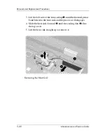
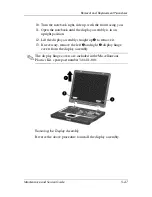
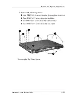
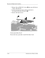
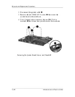
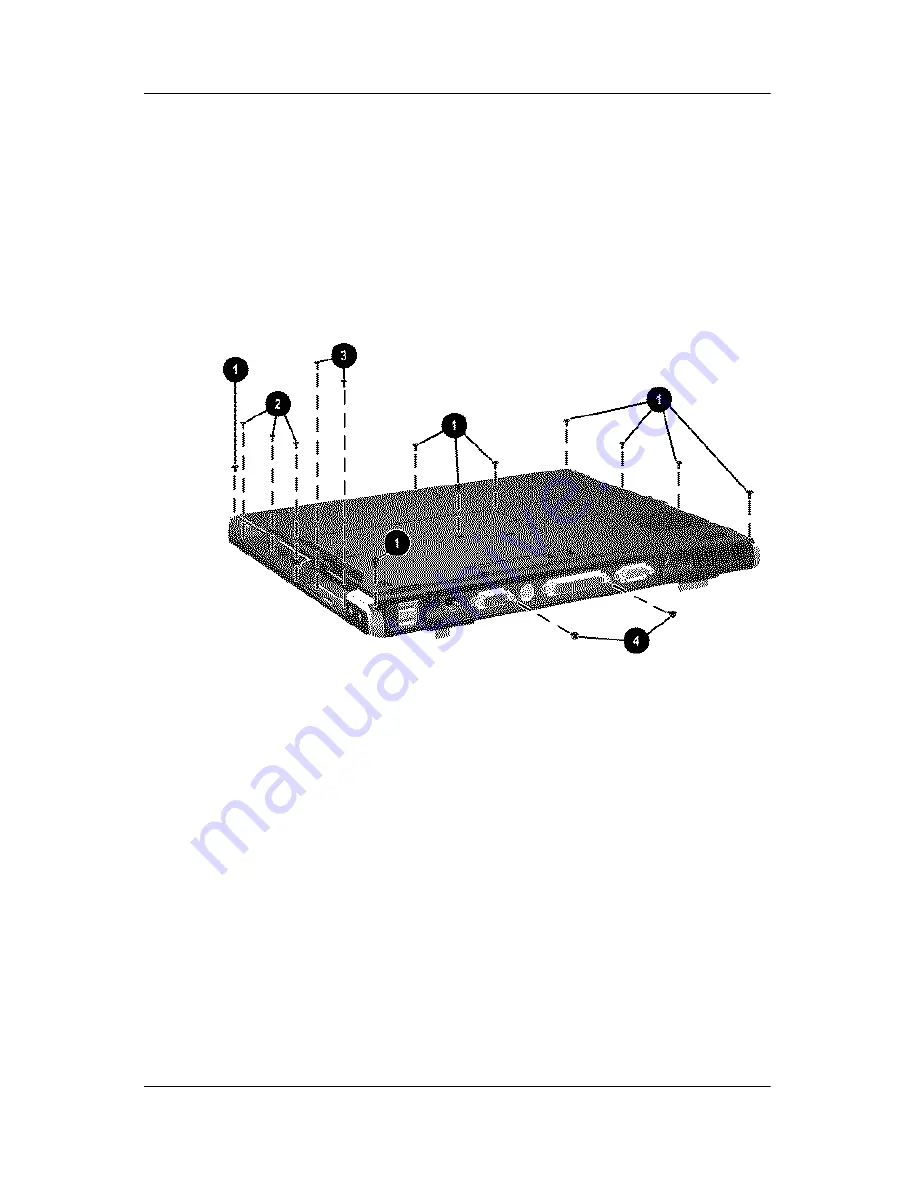
3. Remove the following screws:
1
Nine T8M2.5×9.0 screws from the bottom of the notebook
2
Three PM2.5×3.5 screws from the MultiBay
3
Two PM2.5×3.5 screws from the hard drive bay
4
Two T8M2.5×5.5 screws from the rear panel
Removing the Top Cover Screws
Содержание Compaq nc6000
Страница 26: ...Product Description Maintenance and Service Guide 1 21 Top Components Continued ...
Страница 64: ...3 4 Maintenance and Service Guide Illustrated Parts Catalog Notebook Major Components ...
Страница 66: ...3 6 Maintenance and Service Guide Illustrated Parts Catalog Notebook Major Components ...