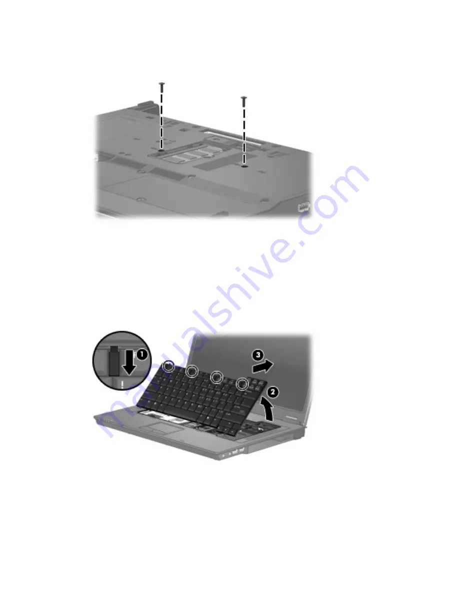
Remove the keyboard:
1
.
Remove the two Torx T8M2.5×9.0 screws that secure the keyboard to the computer.
2
.
Turn the computer display-side up, with the front toward you.
3
.
Open the computer as far as possible.
4
.
Slide the four keyboard retention tabs
(1)
toward you. The tabs are located between the
esc
and
f1
keys, between the
f4
and
f5
keys, between the
f8
and
f9
keys, and between the
f12
and
delete
keys.
5
.
Lift the rear edge of the keyboard
(2)
until it rests at an angle.
6
.
Slide the keyboard back
(3)
until it rests against the display.
36 Chapter
4
Removal and replacement procedures
Содержание Compaq 6720t
Страница 1: ...HP Compaq 6720t Mobile Thin Client Maintenance and Service Guide ...
Страница 4: ...iv Safety warning notice ...
Страница 8: ...viii ...
Страница 48: ...Reverse this procedure to install the heat sink 40 Chapter 4 Removal and replacement procedures ...
Страница 88: ...Where used 2 screws that secure the display assembly right hinge to the computer 80 Chapter 7 Screw listing ...
Страница 90: ...Where used 4 screws that secure the top cover to the base enclosure 82 Chapter 7 Screw listing ...
Страница 93: ...Where used 2 screws that secure the PC Card assembly to the system board Black Phillips PM2 0 4 0 screw 85 ...
Страница 100: ...RJ 11 modem Pin Signal 1 Unused 2 Tip 3 Ring 4 Unused 5 Unused 6 Unused 92 Chapter 8 Connector pin assignments ...
Страница 114: ......


