NOTE:
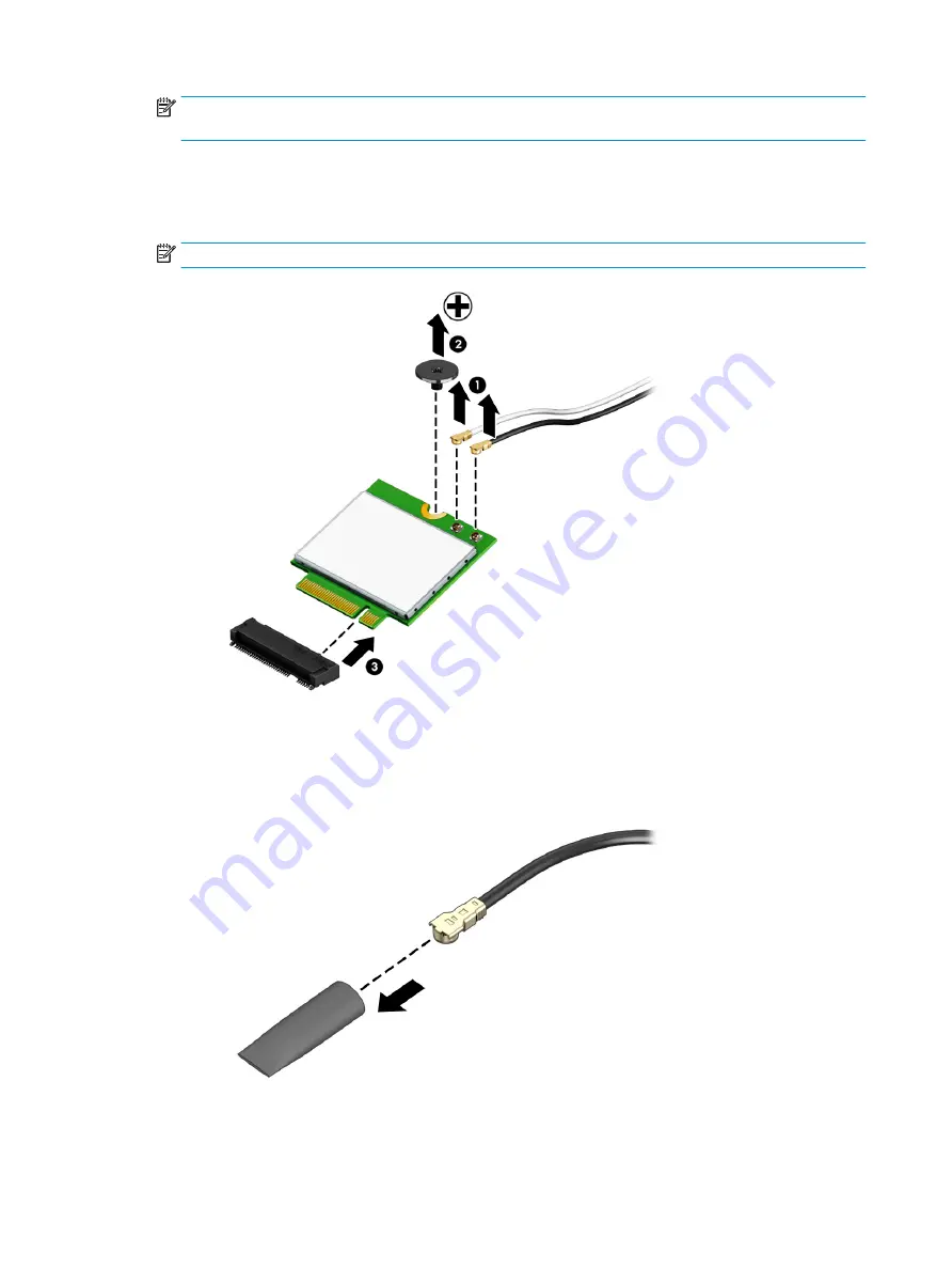
The #1/Main WLAN antenna cable connects to the WLAN module #1/Main terminal. The #2/Aux
WLAN antenna cable connects to the WLAN module #2/Aux terminal.
2.
Remove the Phillips M2.0 × 2.9 screw (2) that secures the WLAN module to the system board. (The WLAN
module tilts up.)
3.
Remove the WLAN module (3) by pulling the module away from the slot at an angle.
NOTE:
WLAN modules are notched to prevent incorrect installation.
4.
If the WLAN antenna is not connected to the terminal on the WLAN module, install a protective sleeve on
the antenna connector, as shown in the following illustration.
Reverse this procedure to install the WLAN module.
32
Chapter 6 Removal and replacement procedures for authorized service provider parts
ENWW
Содержание Chromebox G3
Страница 8: ...4 Chapter 1 Product description ENWW ...
Страница 16: ...12 Chapter 2 Getting to know your Chromebox ENWW ...
Страница 20: ...16 Chapter 3 Illustrated parts catalog ENWW ...
Страница 24: ...20 Chapter 4 Removal and replacement procedures preliminary requirements ENWW ...
Страница 46: ...42 Chapter 6 Removal and replacement procedures for authorized service provider parts ENWW ...
Страница 50: ...46 Chapter 7 Specifications ENWW ...
Страница 54: ...50 Chapter 8 Power cord set requirements ENWW ...
Страница 56: ...52 Chapter 9 Recycling ENWW ...


