background image

Preparation for disassembly

Bottom cover

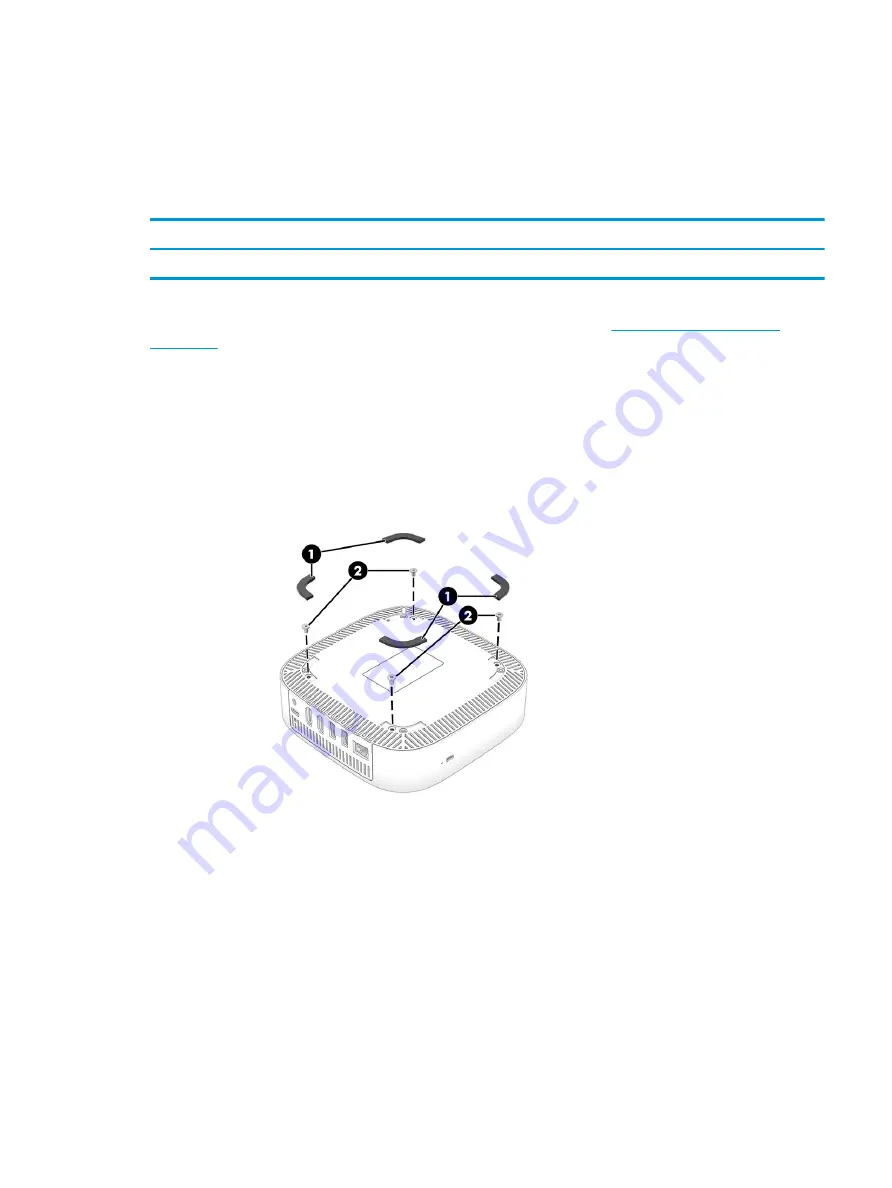
To remove the bottom cover, use this procedure and illustration.

Table 6-1

  Bottom cover description and part number

Description

Spare part number

Bottom cover

L17258-001

Before removing the bottom cover, prepare the Chromebox for disassembly (

Preparation for disassembly 

on page 27

).

Remove the bottom cover:

1.

Position the Chromebox upside down with the rear toward you.

2.

Remove the four rubber feet (1).

The rubber feet are available in the Rubber Feet Kit, spare part number L17271-001.

3.

Remove the four Phillips M2.5 × 5.0 screws (2) that secure the bottom cover to the Chromebox.

4.

Use a case utility tool or similar thin plastic tool (1) to separate the front edge of the bottom cover (2) from 
the Chromebox.

ENWW

Component replacement procedures

27

Содержание Chromebox G3

Страница 1: ...Maintenance and Service Guide SUMMARY This guide provides information about spare parts removal and replacement of parts security backing up and more ...

Страница 2: ...arranty HP shall not be liable for technical or editorial errors or omissions contained herein First Edition November 2020 Document Part Number M27977 001 Product notice This guide describes features that are common to most models Some features may not be available on your Chromebook To access the latest user guides go to http www hp com support and follow the instructions to find your product The...

Страница 3: ...ce considerations 18 Plastic parts 18 Cables and connectors 18 Drive handling 18 Workstation guidelines 18 5 Electrostatic discharge information 21 Generating static electricity 21 Preventing electrostatic damage to equipment 22 Personal grounding methods and equipment 22 Grounding the work area 23 Recommended materials and equipment 23 6 Removal and replacement procedures for authorized service p...

Страница 4: ...y module 33 System board 35 Fan 37 Heat sink 38 Top shield 39 Power button board 40 7 Specifications 43 Chromebook specifications 43 Solid state drive specifications 45 8 Power cord set requirements 47 Requirements for all countries 47 Requirements for specific countries and regions 47 9 Recycling 51 Index 53 iv ENWW ...

Страница 5: ...205U 1 9 GHz processor 2400 MHz FSB dual core 2 MB L3 cache 15 W Chipset Intel integrated soldered on circuit SoC Graphics controller Intel UHD 620 integrated graphics on Chromebook models equipped with an Intel Core i7 or Intel Core i5 processor Intel UHD integrated graphics on Chromebook models equipped with an Intel Core i3 Intel Pentium or Intel Celeron processor Media card reader HP 3 in 1 ca...

Страница 6: ... 5 MU MIMO M 2 2230 non vPro MIPI BRI WW with two antennas 10 100 1000M GbE local area network LAN eMMC 64 GB MO 276 MMC v 5 0 Keyboard pointing devices USB Chrome standalone wired keyboard and mouse combo HP Bluetooth travel mouse HP USB comfort grip wireless mouse HP USB 3 button laser mouse Power requirements AC adapters 90 W HP Smart Adapter 4 5 mm 90 W HP Smart Adapter PFC standard barrel rig...

Страница 7: ...Table 1 1 Product components and their descriptions continued Category Description Operating system Chrome 64 Serviceability End user replaceable part AC adapter ENWW 3 ...

Страница 8: ...4 Chapter 1 Product description ENWW ...

Страница 9: ... designed to act as a deterrent but it might not prevent the Chromebox from being mishandled or stolen 2 Reset recovery button To reset or recover the device insert a paper clip or pushpin into the reset recovery button hole and then press the button NOTE Pressing this button with the power button deletes all account information and data stored on your device such as photos downloaded files and sa...

Страница 10: ...his jack does not support optional standalone microphones WARNING To reduce the risk of personal injury adjust the volume before putting on headphones earbuds or a headset For additional safety information see the Regulatory Safety and Environmental Notices NOTE When a device is connected to the jack the Chromebox speakers are disabled 2 USB SuperSpeed charging port Connects a USB device provides ...

Страница 11: ...e Chromebox When the Chromebox is on press the button briefly to initiate Sleep When the Chromebox is in the Sleep state press the button briefly to exit Sleep select products only When the Chromebox is in Hibernation press the button briefly to exit Hibernation IMPORTANT Pressing and holding down the power button results in the loss of unsaved information If the Chromebox has stopped responding a...

Страница 12: ... adapter purchased separately when charging a small external device 4 HDMI ports 2 Connects an optional video or audio device such as a high definition television any compatible digital or audio component or a high speed High Definition Multimedia Interface HDMI device 5 AC adapter and battery light White The AC adapter is connected and the battery is fully charged Amber The AC adapter is connecte...

Страница 13: ...problems or traveling internationally with the device Labels can be in paper form or imprinted on the product IMPORTANT Check the bottom of the Chromebox for the correct label Service label Provides important information to identify your device When contacting support you might be asked for the serial number the product number or the model number Locate this information before you contact support ...

Страница 14: ...lowing label below represents Asia Pacific and Japan 1 countries and regions The following label below represents Asia Pacific and Japan 2 countries and regions 10 Chapter 2 Getting to know your Chromebox ENWW ...

Страница 15: ...atory information about the device Wireless certification labels Provide information about optional wireless devices and the approval markings for the countries or regions in which the devices have been approved for use ENWW Labels 11 ...

Страница 16: ...12 Chapter 2 Getting to know your Chromebox ENWW ...

Страница 17: ...HP continually improves and changes product parts For complete and current information about supported parts for your Chromebox go to http partsurfer hp com select your country or region and then follow the on screen instructions NOTE Details about your Chromebox including model serial number product key and length of warranty are on the service tag at the bottom of your Chromebox ENWW Chromebox m...

Страница 18: ...769 001 Equipped with an Intel Core i3 10110U processor M24719 001 Equipped with an Intel Pentium 6405U processor and 64 GB on board system memory M25771 001 Equipped with an Intel Pentium 6405U processor and 32 GB on board system memory M24722 001 Equipped with an Intel Celeron 5205U processor and 64 GB on board system memory M25768 001 Equipped with an Intel Celeron 5205U processor and 32 GB on ...

Страница 19: ...91 850 65 W AC adapter non PFC S 3P 4 5 mm 710412 001 Power cord C5 1 0 m 3 3 ft conventional with sticker For use in Australia L19358 001 For use in Brazil L19359 001 For use in Denmark L19360 001 For use in Europe L19361 001 For use in India L19363 001 For use in Israel L19362 001 For use in Italy L19364 001 For use in Japan L19365 001 For use in North America L19367 001 For use in South Africa ...

Страница 20: ...16 Chapter 3 Illustrated parts catalog ENWW ...

Страница 21: ...o disassemble and reassemble the Chromebox Tools required You need the following tools to complete the removal and replacement procedures Tweezers Case utility tool or similar thin nonmarking plastic tool Flat bladed screwdriver Magnetic Phillips P0 and P1 screwdrivers Suction cups ENWW Tools required 17 ...

Страница 22: ...ves are fragile components Handle them with care To prevent damage to the Chromebox damage to a drive or loss of information observe these precautions Before removing or inserting a hard drive shut down the Chromebox If you are unsure whether the Chromebox is off or in Hibernation turn the Chromebox on and then shut it down through the operating system Before handling a drive be sure that you are ...

Страница 23: ...tact dissipative surfaces use fixtures made only of static safe materials Keep the work area free of nonconductive materials such as ordinary plastic assembly aids and polystyrene foam Handle ESD sensitive components parts and assemblies by the case or PCM laminate Handle these items only at static free workstations Avoid contact with pins leads or circuitry Turn off power and input signals before...

Страница 24: ...20 Chapter 4 Removal and replacement procedures preliminary requirements ENWW ...

Страница 25: ...nents observe these precautions Keep components in their electrostatic safe containers until you are ready to install them Before touching an electronic component discharge static electricity by using the guidelines described Personal grounding methods and equipment on page 22 Avoid touching pins leads and circuitry Handle electronic components as little as possible If you remove a component place...

Страница 26: ...roved containers or packaging Keep electrostatic sensitive parts in their containers until they arrive at static free stations Place items on a grounded surface before removing them from their container Always be properly grounded when touching a sensitive component or assembly Avoid contact with pins leads or circuitry Place reusable electrostatic sensitive parts from assemblies in protective pac...

Страница 27: ... inserting and removing connectors or test equipment Use fixtures made of static safe materials when fixtures must directly contact dissipative surfaces Keep the work area free of nonconductive materials such as ordinary plastic assembly aids and polystyrene foam Use conductive field service tools such as cutters screwdrivers and vacuums Avoid contact with pins leads or circuitry Recommended mater...

Страница 28: ...packages Conductive plastic bags Conductive plastic tubes Conductive tote boxes Opaque shielding bags Transparent metallized shielding bags Transparent shielding tubes 24 Chapter 5 Electrostatic discharge information ENWW ...

Страница 29: ...e provider parts IMPORTANT Components described in this chapter should be accessed only by an authorized service provider Accessing these parts can damage the Chromebook or void the warranty NOTE Details about your Chromebook including model serial number product key and length of warranty are on the service tag at the bottom of your Chromebook ENWW 25 ...

Страница 30: ...parts for your Chromebook go to http partsurfer hp com select your country or region and then follow the on screen instructions You must remove replace or loosen as many as 30 screws when you service the parts described in this chapter Make special note of each screw size and location during removal and replacement 26 Chapter 6 Removal and replacement procedures for authorized service provider par...

Страница 31: ...tion for disassembly on page 27 Remove the bottom cover 1 Position the Chromebox upside down with the rear toward you 2 Remove the four rubber feet 1 The rubber feet are available in the Rubber Feet Kit spare part number L17271 001 3 Remove the four Phillips M2 5 5 0 screws 2 that secure the bottom cover to the Chromebox 4 Use a case utility tool or similar thin plastic tool 1 to separate the fron...

Страница 32: ...sassembly on page 27 2 Remove the bottom cover Bottom cover on page 27 Remove the I O side frame 1 Remove the two Phillips M2 5 5 0 screws 1 that secure the I O side frame to the Chromebox 2 Detach the bottom shield rear protective strip 2 from the I O side frame and bottom shield The bottom shield rear protective strip is attached to the I O side frame and bottom shield with double sided adhesive...

Страница 33: ...27 2 Remove the bottom cover Bottom cover on page 27 3 Remove the I O side frame I O side frame on page 28 Remove the bottom shield 1 Remove the four Phillips M2 5 5 0 screws 1 that secure the bottom shield to the Chromebox 2 Detach the bottom shield front protective strip 2 and the bottom shield padding 3 from the bottom shield The bottom shield front protective strip is attached to the bottom sh...

Страница 34: ...r disassembly Preparation for disassembly on page 27 2 Remove the bottom cover Bottom cover on page 27 3 Remove the I O side frame I O side frame on page 28 4 Remove the bottom shield Bottom shield on page 29 Remove the power connector cable 1 Turn the bottom shield right side up with the rear panel toward you 2 Remove the two Phillips M2 5 5 0 screws 1 that secure the power connector cable to the...

Страница 35: ...ss module only with a wireless module authorized for use in the Chromebook by the governmental agency that regulates wireless devices in your country or region If you replace the module and then receive a warning message remove the module to restore device functionality and then contact technical support Before removing the WLAN module follow these steps 1 Prepare the Chromebox for disassembly Pre...

Страница 36: ...ilts up 3 Remove the WLAN module 3 by pulling the module away from the slot at an angle NOTE WLAN modules are notched to prevent incorrect installation 4 If the WLAN antenna is not connected to the terminal on the WLAN module install a protective sleeve on the antenna connector as shown in the following illustration Reverse this procedure to install the WLAN module 32 Chapter 6 Removal and replace...

Страница 37: ... page 27 3 Remove the I O side frame I O side frame on page 28 4 Remove the bottom shield Bottom shield on page 29 Remove the solid state drive 1 Remove the Phillips M2 0 2 9 screw 1 that secures the solid state drive to the system board 2 Remove the solid state drive 2 by sliding it away from the slot at an angle Reverse this procedure to install the solid state drive Memory module To remove the ...

Страница 38: ...29 Remove the memory module 1 Insert a case utility tool or similar thin plastic tool into the openings 1 on either side of the memory module shield and remove the shield 2 The memory module shield is available using spare part number L17264 001 NOTE When installing the memory module shield be sure that the edges of the shield fit securely into the retention clips 3 built into the system board 34 ...

Страница 39: ...subsystem with UMA memory and the Chrome operating system Equipped with an Intel Core i7 10610U processor M24721 001 Equipped with an Intel Core i5 10310U processor and 64 GB on board system memory M25770 001 Equipped with an Intel Core i5 10310U processor M24720 001 Equipped with an Intel Core i3 10110U processor and 64 GB on board system memory M25769 001 Equipped with an Intel Core i3 10110U pr...

Страница 40: ... module see WLAN module on page 31 Solid state drive see Solid state drive on page 33 Memory module and shield see Memory module on page 33 Fan see Fan on page 37 Heat sink see Heat sink on page 38 Remove the system board 1 Disconnect the WLAN antenna cables 1 from the WLAN module terminals NOTE The 1 Main WLAN antenna cable connects to the WLAN module 1 Main terminal The 2 Aux WLAN antenna cable ...

Страница 41: ... to install the system board Fan To remove the fan use these procedures and illustrations Table 6 9 Fan description and part number Description Spare part number Fan includes cable M24727 001 Before removing the fan follow these steps 1 Prepare the Chromebox for disassembly Preparation for disassembly on page 27 2 Remove the bottom cover Bottom cover on page 27 and then remove the following compon...

Страница 42: ...ese procedures and illustrations Table 6 10 Heat sink description and part number Description Spare part number Heat sink 15 W includes replacement thermal material M24726 001 Before removing the heat sink follow these steps 1 Prepare the Chromebox for disassembly Preparation for disassembly on page 27 2 Remove the bottom cover Bottom cover on page 27 and then remove the following components 1 Rem...

Страница 43: ... component 1 and the surface of the heat sink 2 Replacement thermal material is included with the heat sink and system board spare part kits Reverse this procedure to install the heat sink Top shield To remove the top shield use this procedure and illustration Table 6 11 Top shield description and part number Description Spare part number Top shield includes wireless antenna M24725 001 ENWW Compon...

Страница 44: ...to install the top shield Power button board To remove the power button board use these procedures and illustrations Table 6 12 Power button board description and part number Description Spare part number Power button board M24724 001 Before removing the power button board follow these steps 1 Prepare the Chromebox for disassembly Preparation for disassembly on page 27 2 Remove the bottom cover Bo...

Страница 45: ... 2 Remove the power button board 2 3 If it is necessary to replace the power button board cable disconnect the cable from the connector 3 on the power button board The power button board cable is available using spare part number M42089 001 Reverse this procedure to install the power button board ENWW Component replacement procedures 41 ...

Страница 46: ...42 Chapter 6 Removal and replacement procedures for authorized service provider parts ENWW ...

Страница 47: ...romebook the Chromebook dimensions and weights as well as input power ratings and operating specifications provide helpful information Table 7 1 Chromebook specifications Metric U S Dimensions Width 14 9 cm 5 9 in Depth 14 9 cm 5 9 in Height front to back 4 0 cm 1 6 in Weight varies by Chromebook configuration and components 0 6 g 1 4 lb Input power ENWW Chromebook specifications 43 ...

Страница 48: ...31 A 45 W 19 5 V dc 3 33 A 65 W 19 5 V dc 4 62 A 90 W 19 5 V dc 6 15 A 120 W 19 5 V dc 6 9 A 135 W 19 5 V dc 7 70 A 150 W 19 5 V dc 10 3 A 200 W 19 5 V dc 11 8 A 230 W 19 5 V dc 16 92 A 330 W 19 5 V dc 3 33 A 65 W 19 5 V dc 4 62 A 90 W 19 5 V dc 7 70 A 150 W 19 5 V dc 10 3 A 200 W Temperature Operating 5 C to 35 C 41 F to 95 F Nonoperating 20 C to 60 C 4 F to 140 F Relative humidity noncondensing ...

Страница 49: ... 1 ms Transfer rate Sequential read up to 2150 MB s Random read Up to 300 000 IOPs Sequential write up to 1550 MB s Random write Up to 100 000 IOPs Total logical sectors 227 513 216 Operating temperature 0 C to 70 C 32 F to 158 F 1 GB 1 billion bytes when referring to hard drive storage capacity Actual accessible capacity is less Actual drive specifications may differ slightly NOTE Certain restric...

Страница 50: ...46 Chapter 7 Specifications ENWW ...

Страница 51: ...d no more than 2 0 m 6 5 ft All power cord sets must be approved by an acceptable accredited agency responsible for evaluation in the country or region where the power cord set will be used The power cord sets must have a minimum current capacity of 10 A and a nominal voltage rating of 125 V ac or 250 V ac as required by the power system of each country or region The appliance coupler must meet th...

Страница 52: ...IMKO 1 France UTE 1 Germany VDE 1 India BIS 1 Israel SII 1 Italy IMQ 1 Japan JIS 3 Netherlands KEMA 1 New Zealand SANZ 1 Norway NEMKO 1 People s Republic of China CCC 4 Saudi Arabia SASO 7 Singapore PSB 1 South Africa SABS 1 South Korea KTL 5 Sweden SEMKO 1 Switzerland SEV 1 Taiwan BSMI 6 Thailand TISI 1 United Kingdom ASTA 1 48 Chapter 8 Power cord set requirements ENWW ...

Страница 53: ... 3 conductor 0 75 mm or 1 25 mm conductor size The wall plug must be a two pole grounding type with a Japanese Industrial Standard C8303 7 A 125 V ac configuration 4 The flexible cord must be Type RVV 3 conductor 0 75 mm conductor size Power cord set fittings appliance coupler and wall plug must bear the CCC certification mark 5 The flexible cord must be Type H05VV F 3 conductor 0 75 mm conductor ...

Страница 54: ...50 Chapter 8 Power cord set requirements ENWW ...

Страница 55: ...battery in general household waste Follow the local laws and regulations in your area for battery disposal HP encourages customers to recycle used electronic hardware HP original print cartridges and rechargeable batteries For more information about recycling programs see the HP website at http www hp com recycle ENWW 51 ...

Страница 56: ...52 Chapter 9 Recycling ENWW ...

Страница 57: ...abels Bluetooth 9 regulatory 9 serial number 9 service 9 wireless certification 9 WLAN 9 M memory module removal 33 spare part numbers 33 memory module shield removal 34 spare part number 34 P packaging guidelines 17 pointing device product description 2 power button board removal 40 spare part number 40 power button board cable removal 41 spare part number 41 power connector cable removal 30 spar...

Страница 58: ...lid state drive 45 static electricity 17 21 system board removal 35 spare part numbers 35 T top shield removal 39 spare part number 39 transporting guidelines 17 traveling with the Chromebox 9 W wireless certification label 9 WLAN device 9 WLAN label 9 WLAN module removal 31 spare part number 31 workstation guidelines 17 18 54 Index ENWW ...

Отзывы: