Model 5261A
Section II
Paragraphs 2-1 to 2-13
SECTION II
INSTALLATION
2-1.
INITIAL INSPECTION.
2-2
As soon as the Model 5261A is received, verify
that the instrument is intact and as ordered. Inspect the
plug-in for any physical damage such as scratched panel,
broken knob, or bent connectors. If damage is found,
refer to the warranty page at the rear of this manual and
Paragraph 2-5 for shipping and repackaging instructions.
2-3.
STORAGE AND RESHIPMENT.
2-4.
ENVIRONMENT. Conditions during storage
and shipment should be limited as follows:
a.
Maximum temperature 167-F (75
°
C).
b.
Minimum temperature -40-F (-40
°
C).
2-5.
PACKAGING. To protect your instrument
during shipment or storage, use the best packaging
methods available. Your Hewlett-Packard field office
can provide materials similar to those used for original
factory packaging. Contract packaging companies can
provide dependable custom packaging on short notice.
a.
If possible. use the original container
designed for the instrument. Otherwise, use a strong
carton (350 lb/sq inch bursting strength) or wooden box
to house the instrument.
b.
Wrap the instrument in heavy paper or
plastic before placing it in the shipping container.
c.
Use plenty of packing material around all
sides of the instrument and protect the front panel with
cardboard strips.
d. Seal the package with strong tape or metal
bands. Mark with "Delicate Instrument."
e.
Refer to the warranty page at the rear of this
manual and check with your Hewlett-Packard field office
for shipping instructions. All correspondence
should refer to an instrument by model number and the
full, eight-digit serial number.
2-6.
INSTALLATION.
2-7.
To install the Video Amplifier in the compartment
provided at the right side of the counter front panel,
proceed as follows:
a.
Remove AC power from the counter by
rotating the SAMPLE RATE control lull counter
clockwise to POWER OFF.
b.
Loosen locking screws on either side of the
plug-in compartment (or single locking screw on left side
by turning fully counterclockwise.
c.
Remove blank filler panel Or plug-in unit
installed.
d.
Slide the Model 5261A into the
compartment. Make certain the plug-in is properly
aligned and tighten the locking screws.
2-8.
COOLING
2-9.
Tile Video Amplifier plug-in unit is cooled by the
ventilation of the (hp) counter in which it is installed.
Refer to the Operating and Service Manual of the
Counter for cooling system maintenance instructions.
2-10.
POWER REOUIREMENTS
2-11.
All voltages required to operate the Model
5261A are supplied by the circuits of the (hp) counter in
which the plug-in is installed.
2-12.
ELECTRICAL CONNECTIONS.
2-13.
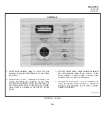
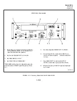
The INPUT terminal on the front panel of the
plug-in (see Figure 3-2) provides the only connection for
the input signal. The front-panel OUTPUT 50
Ω
connector supplies the Video Amplifier output for
monitoring or external equipment. All connections to
the counter are completed through the 50-pin jack at the
rear of the plug-in unit.
2-1/2-2
Содержание AM-4380/U 5261A
Страница 2: ...A ...
Страница 7: ...Model 5261A Section I Figure 1 1 FIGURE 1 1 Model 5261A 1 0 ...
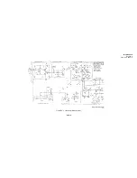
Страница 19: ...Model 5261A Section V Figure 5 1 FIGURE 5 1 Schematic Diagram Notes 5 5 ...
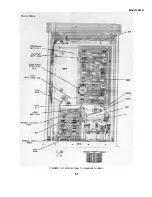
Страница 20: ...Model 5261A Section V Figure 5 2 FIGURE 5 2 Top View Component Location 5 6 ...
Страница 21: ...Model 5261A FIGURE 5 3 Bottom View Component Location 5 7 ...
Страница 22: ...Model 5261A Section V Figure 5 3 and 5 4 FIGURE 5 4 Video Amplifier Schematic 5 7 5 8 ...
Страница 31: ...TM 11 6625 2906 14 P APPENIDIX C Additional Authorization List Not Applicable C 1 ...
Страница 36: ...SECTION IV REMARKS REFERENCE REMARKS CODE A VISUALS B REPLACE FUSES KNOBS ETC C PERFORMANCE TESTS ONLY D 5 ...
Страница 39: ...Model 5261A Appendix E FIGURE A 1 Top View Component Location E 3 ...
Страница 40: ...Model 5261A Appendix E FIGURE A 2 Bottom View Component Location E 4 ...
Страница 41: ...Model 5261A Appendix E FIGURE A 3 Video Amplifier Schematic E 5 ...
Страница 42: ...Model 5261A Appendix E FIGURE A 4 A1 Preamplifier Component Location E 6 ...
Страница 43: ...Model 5261A Appendix E FIGURE A 5 Video Amplifier Schematic E 7 ...
Страница 44: ......
Страница 45: ......
Страница 47: ......
Страница 48: ...PIN 046855 000 ...


