


Model 5261 A
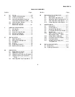
TABLE OF CONTENTS
Section Page
0 0-1. Scope............................................ 0-1
0-2. Indexes of Publications................. 0-1
0-3. Forms and Records....................... 0-1
0-4. Reporting Equipment Improve-
ment Recommendations (EIR)..... 0-1
0-5. Administrative Storage................. 0-1
0-6. Destruction of Army
Electronics Materiel..................... 0-1
I GENERAL INFORNIATION ....................1-1
1-1.
Introduction ....................................1-1
1-2.
Description.....................................1-1
1-4.
Instrument Identification ................1-1
1-6.
Accessory Supplied .......................1-1
1-8.
Accessories Available....................1-1
II INSTALLATION.......................................2-1
2-1.
Initial Inspection .............................2-1
2-3 Storage and Reshipment...............2-1
2-6.
Installation......................................2-1
2-8.
Cooling. .........................................2-1
2-10. Power Requirement.......................2-1
2-12. Electrical Connections ...................2-1
III OPERATION . .........................................3-1
3-1.
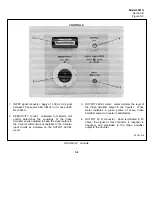
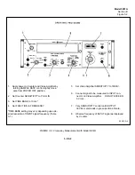
Model 5261A Controls ...................3-1
3-3.
Operating Procedure .....................3-1
3-5.
Operation with Pulse Input Signals3-1
3-7.
Operation with High Impedance ....3-1
Probe ........................................3-1
3-9.
Video Amplifier Input Impedance...3-1
Section Page
IV PRINCIPLES OF OPERATION .............. 4-1
4-1. Introduction ................................ 4-1
4-3. Preamplifier Assembly Al1......... 4-1
4-5. Attenuator Switch Assembly A2 4-1
4-7. Video Amplifier Assembly A3. ... 4-1
4-10. Output Amplifier Assembly A4... 4-1
V MAINTENANCE...................................... 5-1
5-1. Introduction ................................ 5-1
5-3. Test Equipment ......................... 5-1
5-5. Assembly Identification.............. 5-1
5-7. In-Cabinet Performance Check . 5-1
5-9. Adjustments. .............................. 5-1
5-10. High Frequency Response
Adjustments A3C4. A3Cll ....... 5-1
5-12. Output Meter Calibration . . 5-1
5-14. Troubleshooting and Repair ...... 5-3
5-15. Troubleshooting ......................... 5-3
5-17. Printed Circuit Component
Replacement ........................... 5-3
VI REPLACEABLE PARTS......................... 6-3
6-1. Introduction ..................................... 6-4
6-4. Ordering Information ....................... 6-5
ii
Содержание AM-4380/U 5261A
Страница 2: ...A ...
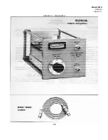
Страница 7: ...Model 5261A Section I Figure 1 1 FIGURE 1 1 Model 5261A 1 0 ...
Страница 19: ...Model 5261A Section V Figure 5 1 FIGURE 5 1 Schematic Diagram Notes 5 5 ...
Страница 20: ...Model 5261A Section V Figure 5 2 FIGURE 5 2 Top View Component Location 5 6 ...
Страница 21: ...Model 5261A FIGURE 5 3 Bottom View Component Location 5 7 ...
Страница 22: ...Model 5261A Section V Figure 5 3 and 5 4 FIGURE 5 4 Video Amplifier Schematic 5 7 5 8 ...
Страница 31: ...TM 11 6625 2906 14 P APPENIDIX C Additional Authorization List Not Applicable C 1 ...
Страница 36: ...SECTION IV REMARKS REFERENCE REMARKS CODE A VISUALS B REPLACE FUSES KNOBS ETC C PERFORMANCE TESTS ONLY D 5 ...
Страница 39: ...Model 5261A Appendix E FIGURE A 1 Top View Component Location E 3 ...
Страница 40: ...Model 5261A Appendix E FIGURE A 2 Bottom View Component Location E 4 ...
Страница 41: ...Model 5261A Appendix E FIGURE A 3 Video Amplifier Schematic E 5 ...
Страница 42: ...Model 5261A Appendix E FIGURE A 4 A1 Preamplifier Component Location E 6 ...
Страница 43: ...Model 5261A Appendix E FIGURE A 5 Video Amplifier Schematic E 7 ...
Страница 44: ......
Страница 45: ......
Страница 47: ......
Страница 48: ...PIN 046855 000 ...


