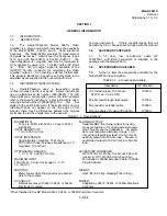


Model 5261A
Section V
Table 5-3
leads in place. Heat may be applied to either side of
board. A heat sink (longnose pliers, commercial heat-
sink tweezers, etc.) should be used when replacing
transistors and diodes to prevent conducting excessive
heat from the soldering iron to the component.
d. Through-hole plating breaks are indicated by
the separation from the board of the round conductor
pads against board and solder replacement component
lead to conductor pads on both sides of the board.
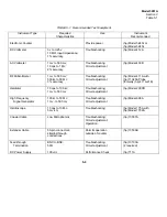
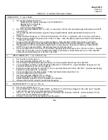
TABLE 5-3. Troubleshooting
Trouble Symptom
Possible Cause
No output to Counter or 50
Ω
OUTPUT
DC voltages from Counter, FET A1Q1 dead,
jack
A4Q4 shorted, P6(1) or J2 shorted
Low Video Amplifier gain
AQ1 weak, A3Q1-A3Q6 weak, A4R5 increased
value
Output low at frequencies near 10 cps
A4C6 open, A1C1, A3R18 increased value
Output Iow at frequencies above 100 kc
A2C1 changed value, high frequency trimmers
A3C4 and A3C11 not correctly adjusted
Output noisy
A1Q1 noisy poor ground connection at P6(3),
A3C5 ,or A3C12 changed value
5-4
Содержание AM-4380/U 5261A
Страница 2: ...A ...
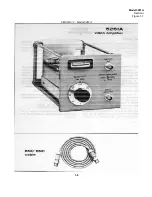
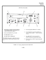
Страница 7: ...Model 5261A Section I Figure 1 1 FIGURE 1 1 Model 5261A 1 0 ...
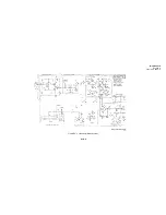
Страница 19: ...Model 5261A Section V Figure 5 1 FIGURE 5 1 Schematic Diagram Notes 5 5 ...
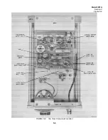
Страница 20: ...Model 5261A Section V Figure 5 2 FIGURE 5 2 Top View Component Location 5 6 ...
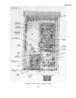
Страница 21: ...Model 5261A FIGURE 5 3 Bottom View Component Location 5 7 ...
Страница 22: ...Model 5261A Section V Figure 5 3 and 5 4 FIGURE 5 4 Video Amplifier Schematic 5 7 5 8 ...
Страница 31: ...TM 11 6625 2906 14 P APPENIDIX C Additional Authorization List Not Applicable C 1 ...
Страница 36: ...SECTION IV REMARKS REFERENCE REMARKS CODE A VISUALS B REPLACE FUSES KNOBS ETC C PERFORMANCE TESTS ONLY D 5 ...
Страница 39: ...Model 5261A Appendix E FIGURE A 1 Top View Component Location E 3 ...
Страница 40: ...Model 5261A Appendix E FIGURE A 2 Bottom View Component Location E 4 ...
Страница 41: ...Model 5261A Appendix E FIGURE A 3 Video Amplifier Schematic E 5 ...
Страница 42: ...Model 5261A Appendix E FIGURE A 4 A1 Preamplifier Component Location E 6 ...
Страница 43: ...Model 5261A Appendix E FIGURE A 5 Video Amplifier Schematic E 7 ...
Страница 44: ......
Страница 45: ......
Страница 47: ......
Страница 48: ...PIN 046855 000 ...


