


HP 8517B S-Parameter Test Set Manual
3-17
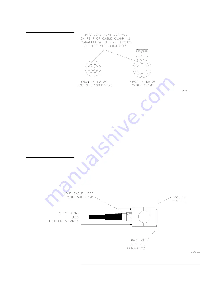
NOTE
The flats may actually be in any orientation, with respect to the front panel.
Figure 3-6
Visually Aligning Clamp and Nut Flats
Positioning the connector
See Figure 3-7. Maneuver the clamp over the RF connector and onto the test
port connector.
1. Hold the test cable with one hand. Use the other hand to press the clamp
gently and steadily, as you wiggle it into position straight over the RF
connector and onto the test port connector nut.
NOTE
Be sure to loosen the clamp when you are slipping it over the connector.
2. Fit the internal flats in the clamp over the flats on the test port connector
nut.
3. Avoid rotating the clamp as you position it so the RF connection remains
tight (remember it loosens easily).
Figure 3-7
Mating the Clamp and Nut Flats
Содержание 8517B
Страница 10: ...x HP 8517B S Parameter Test Set Manual ...
Страница 16: ...Contents 6 HP 8517B S Parameter Test Set Manual ...
Страница 30: ...1 14 HP 8517B S Parameter Test Set Manual Getting Started Operating and Safety Precautions ...
Страница 38: ...2 8 HP 8517B S Parameter Test Set Manual Installation Packaging the Test Set ...
Страница 57: ...HP 8517B S Parameter Test Set Manual 1 ...
Страница 60: ...HP 8517B S Parameter Test Set Manual 4 4 Specifications ...
Страница 84: ...5 24 HP 8517B S Parameter Test Set Manual Troubleshooting the Test Set Troubleshooting Procedures ...
Страница 109: ...HP 8517B S Parameter Test Set Manual 7 11 HP 8517B Replaceable Parts Figure 7 1 Power Cable and Plug Part Numbers ...
Страница 121: ...HP 8517B S Parameter Test Set Manual 7 23 HP 8517B Replaceable Parts Figure 7 4 Detailed Views of Hardware Stack Ups ...