Monitor
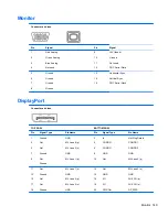
Connector and Icon
Pin
Signal
Pin
Signal
1
2
3
4
Red Analog
Green Analog
Blue Analog
Not used
9
10
11
12
+5V (fused)
Ground
Not used
DDC Serial Data
5
6
7
8
Ground
Ground
Ground
Ground
13
14
15
Horizontal Sync
Vertical Sync
DDC Serial Clock
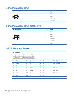
DisplayPort
Connector and Icon
TOP ROW
BOTTOM ROW
Pin
Signal Type
Pin Name
Pin
Signal Type
Pin Name
1
3
5
7
9
Ground
Out
Out
Ground
Out
Ground
GND
ML Lane 0 (p)
ML Lane 0 (n)
GND
ML Lane 1 (p)
2
4
6
8
10
In
CONFIG
CONFIG
GND
Out
Hot Plug Detect
CONFIG 1
CONFIG 2
GND
ML Lane 3 (p)
11
13
15
17
19
Out
Ground
Out
Out
Ground
ML Lane 1 (n)
GND
ML Lane 2 (p)
ML Lane 2 (n)
GND
12
14
16
18
20
Out
GND
I/O
I/O
PWR Out
ML Lane 3 (n)
GND
AUX CH (p)
AUX CH (n)
DP_PWR
Monitor 149

