


54
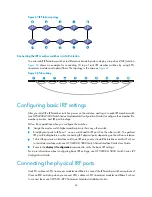
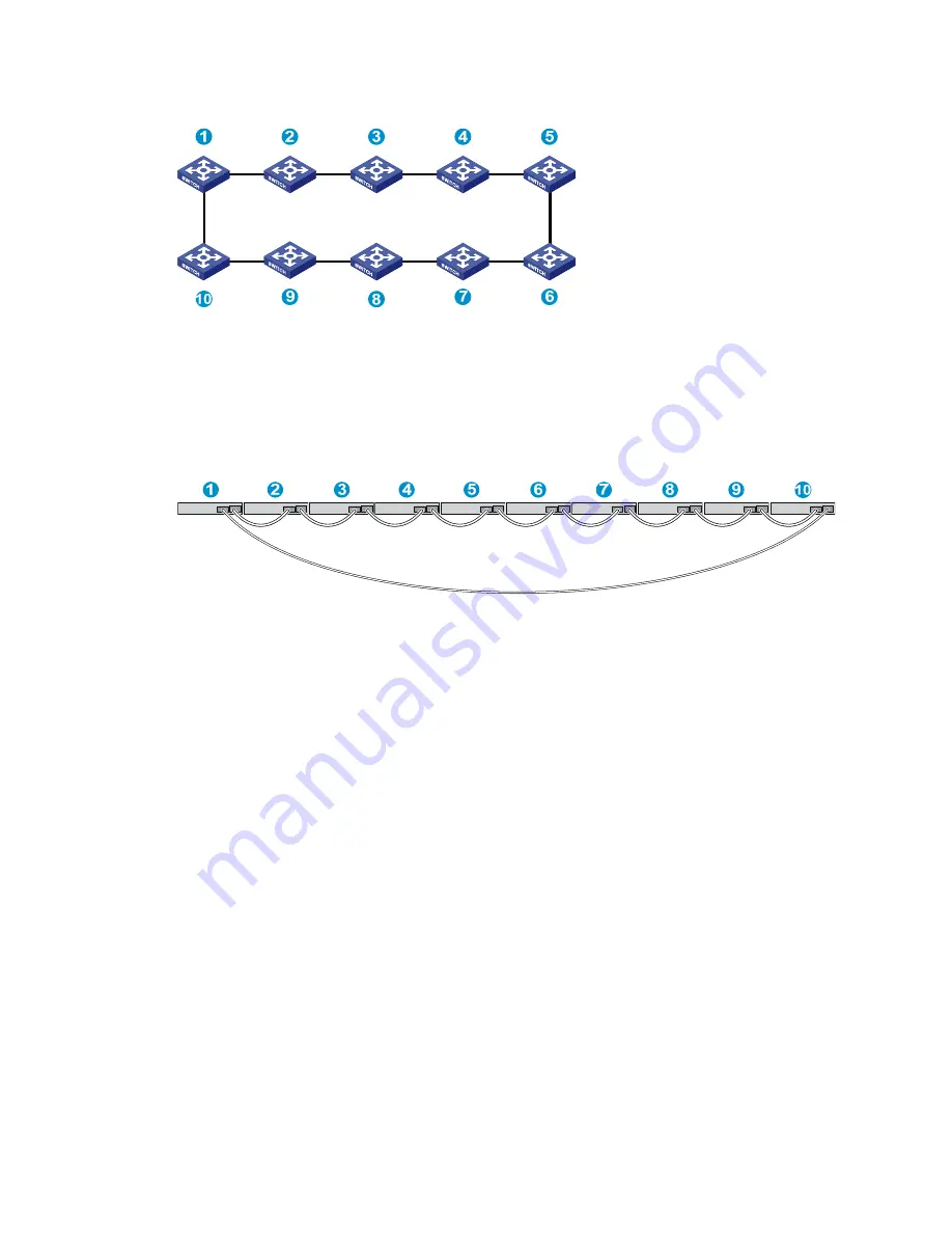
Figure 67
IRF fabric topology
Connecting the IRF member switches in a ToR solution
You can install IRF member switches in different racks side by side to deploy a top of rack (ToR) solution.
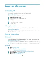
Figure 68
shows an example for connecting 10 top of rack IRF member switches by using SFP+
transceiver modules and optical fibers. The topology is the same as
Figure 67
.
Figure 68
ToR cabling
Configuring basic IRF settings
After you install the IRF member switches, power on the switches, and log in to each IRF member switch
(see
HP 5820X & 5800 Switch Series Fundamentals Configuration Guide
) to configure their member IDs,
member priorities, and IRF port bindings.
Follow these guidelines when you configure the switches:
•
Assign the master switch higher member priority than any other switch.
•
Bind physical ports to IRF port 1 on one switch and to IRF port 2 on the other switch. You perform
IRF port binding before or after connecting IRF physical ports depending on the software release.
•
To bind the ports on an interface card to an IRF port, you must install the interface card first. For how
to install an interface card, see
HP 5820X & 5800 Switch Series Interface Cards User Guide
.
•
Execute the
display irf configuration
command to verify the basic IRF settings.
For more information about configuring basic IRF settings, see
HP 5820X & 5800 Switch Series IRF
Configuration Guide
.
Connecting the physical IRF ports
Use SFP+ cables or SFP+ transceiver modules and fibers to connect the IRF member switches as planned.
Wear an ESD wrist strap when you connect SFP+ cables or SFP+ transceiver modules and fibers. For how
to connect them, see
SFP/SFP+/XFP Transceiver Modules Installation Guide
.


