


49
You can affect the election result by assigning a high member priority to the intended master switch.
For more information about master election, see
HP 5820X & 5800 Switch Series IRF
Configuration Guide
.
•
Prepare an IRF member ID assignment scheme. An IRF fabric uses member IDs to uniquely identify
and manage its members, and you must assign each IRF member switch a unique member ID.
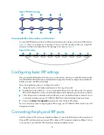
Planning IRF topology and connections
You can create an IRF fabric in daisy chain topology, or more reliably, ring topology. In ring topology,
the failure of one IRF link does not cause the IRF fabric to split as in daisy chain topology. Rather, the IRF
fabric changes to a daisy chain topology without interrupting network services.
You connect the IRF member switches through IRF ports, the logical interfaces for the connections
between IRF member switches. Each IRF member switch has two IRF ports: IRF-port 1 and IRF-port 2. To
use an IRF port, you must bind at least one physical port to it.
When connecting two neighboring IRF member switches, you must connect the physical ports of IRF-port
1 on one switch to the physical ports of IRF-port 2 on the other switch.
The 5800 and 5820X switches can provide 10-GE IRF connections through SFP+ ports, and you can
bind several SFP+ ports to an IRF port for increased bandwidth and availability.
Figure 64
and
Figure 65
show the topologies of an IRF fabric made up of three 5800-24G switches that
use the LSW1SP4P0 interface card for IRF connections. The IRF port connections in the two figures are for
illustration only, and more connection methods are available.
For information about the physical ports available for IRF connections on the 5800 and 5820X switches,
see
Table 8
.
Figure 64
IRF fabric in daisy chain topology


