5.
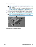
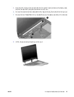
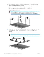
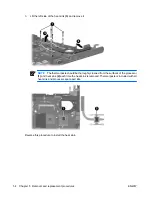
Disconnect the display cable connector
(1)
from the system board and remove the display cable
(2)
from the clips and routing channel built into the top cover.
6.
Remove the wireless antenna cables
(3)
from the clips and routing channel built into the top cover.
7.
Remove the two Phillips PM2.0×9.0 screws
(4)
that secure the display assembly to the computer.
8.
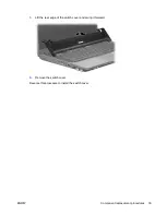
Lift the display assembly straight up and remove it.
ENWW
Component replacement procedures
45
Содержание 510 - Notebook PC
Страница 1: ...HP 510 Notebook PC Maintenance and Service Guide ...
Страница 6: ...vi ENWW ...
Страница 109: ...Universal Serial Bus Pin Signal 1 5 VDC 2 Data 3 Data 4 Ground ENWW Universal Serial Bus 103 ...
Страница 123: ......

