TM 11-6625-2495-14&P
specifies, by the listing of a "work time" figure the
appropriate subcolumn(s), the lowest level of
maintenance authorized to perform the function listed in
column 3. This figure represents the active time required
to perform that maintenance function at the indicated
category of maintenance. If the number or complexity of
the tasks within the listed maintenance function vary at
different maintenance categories, appropriate "work
time" figures will be shown for each category. The
number of task-hours specified by the "work time" figure
represents the average time required to restore an item
(assembly, subassembly, component, module, end item
or system) to a serviceable condition under typical field
operating conditions. This time includes preparation
time, troubleshooting time, and quality assurance/quality
control time in addition to the time required to perform
the specific tasks identified for the maintenance
functions authorized in the maintenance allocation chart.
Subcolumns of column 4 are as follows:
C -- Operator/Crew
O -- Organizational
F -- Direct Support
H -- General Support
D -- Depot
e. Column 5, Tools and Equipment.
Column 5
specifies by code, those common tool sets (not individual
tools) and special tools, test, and support equipment
required to perform the designated function.
f. Column 6, Remarks.
Column 6 contains an
alphabetic code which leads to the remark in section IV,
remarks, which is pertinent to the item opposite the
particular code.
D-4. Tool and Test Equipment Requirements (Sec III)
a. Tool or Test Equipment Reference Code
. The
numbers in this column coincide with the numbers used
in the tools and equipment column of the MAC.
The numbers indicate the applicable tool or test
equipment for the maintenance functions.
b. Maintenance Category.
The codes in this
column indicate the maintenance category allocated the
tool or test equipment.
c. Nomenclature.
This column lists the noun name
and nomenclature of the tools and test equipment
required to perform the maintenance functions.
d. National/NATO Stock Number.
This column lists
the National/NATO stock number of the specific tool or
test equipment.
e. Tool Number.
This column lists the
manufacturer’s part number of the tool followed by the
Federal Supply Code for manufacturers (5-digit) in
parentheses.
D-5. Remarks (Sec IV)
a. Reference Code.
This code refers to the
appropriate item in section II, column 6.
b. Remarks.
This column provides the required
explanatory information necessary to clarify items
appearing in section II.
(Next printed page is D-3)
D-2
Содержание 3300A
Страница 31: ...Model 3300A Section VI Figure 6 1 3300A Top and Bottom Views 6 2 ...
Страница 32: ...Model 3300A Section VI Figure 6 2 Oscillator Circuit Schematic A11 A13 and A14 6 3 ...
Страница 33: ...Model 3300A Section VI Figure 6 4 Output Amplifiers Schematic A15 and A16 6 5 6 6 ...
Страница 34: ...TM 11 6625 2495 14 P THIS PAGE CURRENTLY NOT AVAILABLE FOR DIGITIZATION PAGE Figure 6 3 6 4 ...
Страница 35: ...Model 3300A Section VI Figure 6 5 Power Supply Schematic A12 and A11 6 7 6 8 ...
Страница 36: ...Model 3300A Section VI Figure 6 6 J6 Plug In Receptacle 6 9 ...
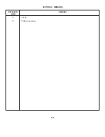
Страница 58: ...SECTION IV REMARKS REFERENCE REMARKS CODE A Visuals B Performance checks D 5 ...
Страница 60: ......
Страница 61: ...PIN 046175 000 ...

