background image

Switch Features

22

Edge Switch 2/24 Installation Guide

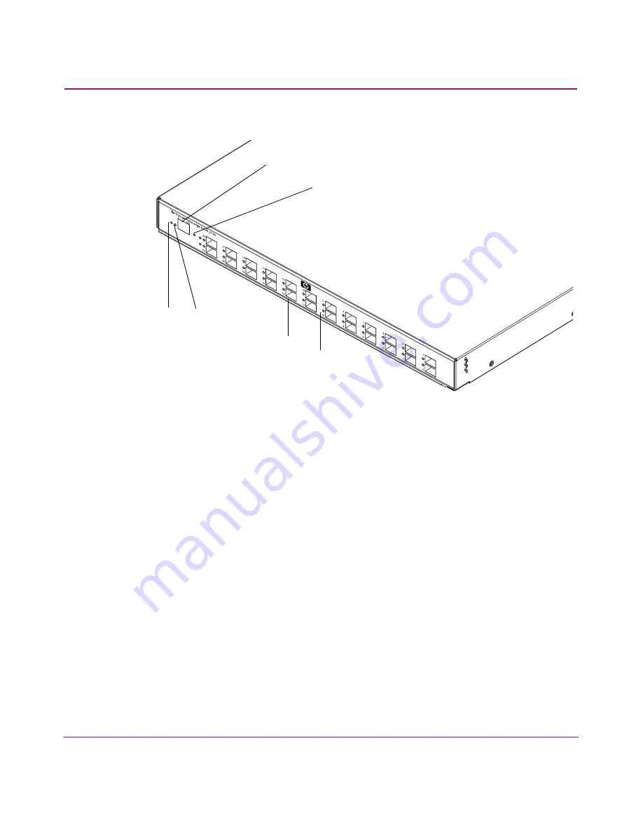
Figure 2

 shows the front panel controls, connectors and indicators.

Figure 2:  Edge Switch 2/24 front panel features

Power and System Error LEDs

The Power LED, as shown in 

Figure 2

, illuminates when the switch is connected 

to facility AC power and powered on. If the LED extinguishes, a facility power 
source, power cord, or power distribution failure is indicated.

The Error LED, as shown in 

Figure 2

, illuminates when the switch detects an 

event requiring immediate operator attention, such as a FRU failure. The LED 
remains illuminated as long as an event is active. The LED extinguishes when the 
Clear System Error Light function is selected from the Product Manager 
application. 

The LED blinks if unit beaconing is enabled. An illuminated LED (indicating a 
failure) takes precedence over unit beaconing. The LED also blinks (at twice the 
beaconing rate) when the IML/RESET button is pressed and held for more than 
three seconds.

1

Power LED (green)

2

Error LED (amber

3

Ethernet LAN connector

4

Initial machine load (IML) button

5

SFP fiber optic connectors

6

Port LEDs

3

1

2

4

5

6

Содержание 316095-B21 - StorageWorks Edge Switch 2/24

Страница 1: ...ks Edge Switch 2 24 Product Version FW v06 xx HAFM SW v08 02 00 Third Edition July 2004 Part Number AA RTDWC TE 958 000283 002 This guide provides procedures for installing configuring and managing the HP StorageWorks Edge Switch 2 24 ...

Страница 2: ...rranty HP shall not be liable for technical or editorial errors or omissions contained herein IBM and AIX are trade marks or registered trade marks of IBM Intel is a U S registered trademarks of Intel Corporation Java is a trademark of Sun Microsystems Inc Linux is a U S registered trademark of Linus Torvalds Microsoft Windows and Windows NT are U S registered trademarks of Microsoft Corporation R...

Страница 3: ...16 HP Storage Web site 17 HP Authorized Reseller 17 1 Switch Features 19 Edge Switch 2 24 Description 20 Field Replaceable Units FRUs 21 Front Panel Features 21 Power and System Error LEDs 22 Ethernet LAN Connector 23 Initial Machine Load Button 23 SFP Transceivers Fibre Channel Ports 23 Port LEDs 24 Rear Panel Features 25 Power Supplies 25 Maintenance Port 26 Switch Management 27 Embedded Web Ser...

Страница 4: ... Rails on the Sides of the Switch 43 Installing the Switch in the Cabinet 45 3 Installing and Configuring the Edge Switch 2 24 47 Installation Options 48 Review Installation Requirements 49 Unpack and Inspect the Switch 50 Install the Edge Switch on a Desktop 51 Configure Switch Network Information 53 Changing the Switch Address 53 LAN Connect the Switch 58 Configure the HAFM Appliance 59 Record o...

Страница 5: ...igure and Enable Ethernet Events 79 Configure Enable and Test Call Home Event Notification 80 Configure Threshold Alerts 81 Create New Alerts 82 Modify Alerts 86 Activate or Deactivate Alerts 87 Delete Alerts 87 Test Remote Notification 87 Back Up HAFM Configuration Data 88 Configure Open Systems Management Appliance 88 Configure Feature Key 88 Configure Open Trunking 88 Enable Embedded Web Server...

Страница 6: ...rmware Version 115 Modify a Firmware Version Description 118 Delete a Firmware Version 119 Download a Firmware Version to a Switch 120 Back Up the Configuration 123 A Regulatory Compliance Notices 125 Regulatory Compliance ID Numbers 126 Federal Communications Commission Notice 127 Class A Equipment 127 Class B Equipment 127 Declaration of Conformity for Products Marked with FCC Logo U S Only 128 ...

Страница 7: ...rackets included in kit 41 6 Attaching the slide rail to the switch 44 7 Connection Description dialog box 54 8 Connect To dialog box 55 9 Port Settings dialog box 55 10 HyperTerminal window 56 11 Disconnect Now dialog box 57 12 Save Session dialog box 57 13 Discover Setup dialog box 59 14 Domain Information dialog box IP Address Page 60 15 Switch Hardware View page 62 16 Configure Date and Time d...

Страница 8: ...interface View window 97 38 Block or unblock a port from the Configure window 98 39 Configure Switch Identification tab 100 40 Switch page Date Time tab 101 41 Switch page Parameters tab 102 42 Switch page Fabric parameters tab 104 43 Switch page Network tab 106 44 Network configuration changes activated 107 45 Management page SNMP tab 108 46 Management page CLI tab 110 47 Security page User Right...

Страница 9: ... 24 Installation Guide 5 Switch Factory Default Values for Reset Configuration Option 138 6 Dimensions 140 7 Environmental Specifications 141 8 Power Requirements 142 9 Operating Tolerances 143 10 Laser Specifications 2 Gb 144 ...

Страница 10: ...Contents 10 Edge Switch 2 24 Installation Guide ...

Страница 11: ...s Guide About this Guide This installation guide provides information to help you Install the Edge Switch 2 24 Perform initial configuration of the switch About this Guide topics include Overview page 12 Conventions page 12 Rack stability page 16 Getting help page 16 ...

Страница 12: ...list of corresponding documentation included with this product see the Related Documents section of the HP StorageWorks Edge Switch 2 24 Release Notes For the latest information documentation and firmware releases please visit the HP StorageWorks web site http h18006 www1 hp com storage saninfrastructure html For information about Fibre Channel standards visit the Fibre Channel Industry Associatio...

Страница 13: ...to follow directions could result in damage to equipment or data Tip Text in a tip provides additional help to readers by providing nonessential or optional techniques procedures or shortcuts Table 1 Document conventions Convention Element Blue text Figure 1 Cross reference links Bold Menu items buttons and key tab and box names Italics Text emphasis and document titles in body text Monospace font...

Страница 14: ...erator serviceable parts WARNING To reduce the risk of personal injury from electrical shock hazards do not open this enclosure Any RJ 45 receptacle marked with these symbols indicates a network interface connection WARNING To reduce the risk of electrical shock fire or damage to the equipment do not plug telephone or telecommunications connectors into this receptacle Any surface or area of the eq...

Страница 15: ...l shock remove all power cords to completely disconnect power from the power supplies and systems Any product or assembly marked with these symbols indicates that the component exceeds the recommended weight for one individual to handle safely WARNING To reduce the risk of personal injury or damage to the equipment observe local occupational health and safety requirements and guidelines for manual...

Страница 16: ...n one rack component is extended for any reason Getting help If you still have a question after reading this guide contact an HP authorized service provider or access our web site http www hp com HP technical support Telephone numbers for worldwide technical support are listed on the following HP web site http www hp com support From this web site select the country of origin Note For continuous q...

Страница 17: ...rs Access storage at http www hp com country us eng prodserv storage html From this web site select the appropriate product or solution HP Authorized Reseller For the name of your nearest HP authorized reseller In the United States call 1 800 345 1518 In Canada call 1 800 263 5868 Elsewhere see the HP web site for locations and telephone numbers http www hp com ...

Страница 18: ...About this Guide 18 Edge Switch 2 24 Installation Guide ...

Страница 19: ...to become data centric A SAN provides speed high capacity and flexibility for the enterprise and is primarily based upon Fibre Channel architecture The switch implements Fibre Channel technology that provides a bandwidth of 2 125 Gbps redundant switched data paths a scalable number of active ports and long transmission distances This chapter describes the switch and attached HP StorageWorks HA Fab...

Страница 20: ...The switch shown in Figure 1 on page 21 provides dynamic switched connections for servers and devices supports mainframe and open systems interconnection OSI computing environments and provides data transmission and flow control between device node ports N_Ports as dictated by the Fibre Channel Physical and Signaling Interface FC PH 4 3 Through interswitch links ISLs the switch can connect additio...

Страница 21: ...form factor pluggable SFP optical transceivers and power supply assemblies with internal cooling fans Edge Switch 2 24 FRUs are detailed in the front and rear panel feature descriptions Front Panel Features Connectors and indicators include the Combined initial machine load and reset IML RESET button Ethernet LAN connector Green power PWR and amber system error ERR LEDs Green blue and amber status...

Страница 22: ...s when the switch detects an event requiring immediate operator attention such as a FRU failure The LED remains illuminated as long as an event is active The LED extinguishes when the Clear System Error Light function is selected from the Product Manager application The LED blinks if unit beaconing is enabled An illuminated LED indicating a failure takes precedence over unit beaconing The LED also...

Страница 23: ...nd held for ten seconds the switch performs a reset After three seconds the ERR LED blinks at twice the unit beaconing rate A reset is disruptive and resets the Microprocessor and functional logic for the CTP card and reloads the firmware from FLASH memory Ethernet LAN interface causing the connection to the HAFM appliance to drop momentarily until the connection automatically recovers Ports causi...

Страница 24: ...rough 9 micron single mode fiber Extended longwave laser Two types of extended longwave laser transceivers provide connections for transferring 2 125 Gbps data up to 20 kilometers or 35 kilometers through 9 micron single mode fiber Port LEDs Amber and green blue LEDs to the left of each Fibre Channel port illuminate extinguish or blink to indicate port status and port speed Amber LED illuminates i...

Страница 25: ...er supply assemblies step down and rectify facility input power to provide 3 3 volts direct current VDC 5 VDC and 12 VDC to the control processor CTP card The power supplies also provide input filtering overvoltage protection and overcurrent protection An amber LED on each assembly illuminates if the FRU fails Either power supply can be replaced while the switch is operational Each power supply ha...

Страница 26: ...nd replaced as part of the integrated power supply Power supply requirements are listed in Technical Specifications on page 133 Maintenance Port The rear panel provides a 9 pin DSUB maintenance port as shown in Figure 3 on page 25 that provides a connection for a local terminal or dial in connection for a remote terminal Although the port is typically used by authorized maintenance personnel opera...

Страница 27: ...f control for up to 48 edge switches or directors Customer supplied remote workstation communicating with the HAFM appliance through a corporate intranet Embedded Web Server EWS Administrators or operators with a browser capable PC and a LAN to which the switch is connected can monitor and manage the switch through the Embedded Web Server EWS interface The EWS interface manages only a single switc...

Страница 28: ...t HAFM appliance intervention an attached server should operate at all times to monitor switch operation log events and configuration changes and report failures The HAFM appliance provides an auto detecting 10 100 Mbps LAN connection to the customer s public intranet to allow access from remote user workstations Remote Workstations Using a standard web browser the HAFM and client applications can...

Страница 29: ...d and using the Microsoft Windows 2000 with Service Pack 4 Windows XP Windows NT 4 0 with Service Pack 6a or Windows Server 2003 Unix workstation with color monitor keyboard and mouse using a Linux based system using an Intel Pentium III processor with 1 GHZ or greater clock speed using Red Hat 7 3 or later operating system Hewlett Packard HA PA RISC processor with a 400 MHz or greater clock speed...

Страница 30: ...uring a Telnet session with the switch The primary purpose of the CLI is to automate management of a large number of switches using scripts The CLI is not an interactive interface no checking is done for pre existing conditions and no prompts display to guide users through tasks Refer to HP StorageWorks CLI Reference Guide for Directors and Edge Switches for more information ...

Страница 31: ...gs that display switch Ethernet link and Fibre Channel link status at the EWS interface HAFM appliance or remote workstation Diagnostic software that performs power on self tests POSTs and port diagnostics loopback tests An RS 232 maintenance port at the rear of the switch port access is password protected that enables installation or service personnel to change the switch s IP address subnet mask...

Страница 32: ...he EWS interface and Element Manager to receive unsolicited SNMP trap messages The trap messages indicate product operational state changes and failure conditions Optional SNMP management using the Fibre Alliance MIB that runs on the HAFM appliance Up to 12 authorized management workstations can be configured through the HAFM server to receive unsolicited SNMP trap messages The trap messages indic...

Страница 33: ...only applications as shown in Figure 4 Figure 4 Management appliance main window The main window provides Menu bar Commands at the top of the window provide drop down menu selections to perform functions for SAN devices including editing viewing planning discovery configuration and monitoring Tool bar The tool bar below the menu bar provides button selections to perform SAN management tasks includ...

Страница 34: ...plains percent utilization for links depicted on the physical map Minimap The minimap at the lower right corner of the window displays the entire SAN topology and provides an aid to navigate the more detailed physical map Status bar The status bar at the bottom of the window displays connection status client information user level and discovery status Zoning The switch supports a name server zonin...

Страница 35: ... numbers is not Zones are grouped into zone sets A zone set is a group of zones that is enabled activated or disabled across all switches in a multi switch fabric Only one zone set can be enabled at one time Multi Switch Fabrics A Fibre Channel topology that consists of one or more interconnected switches or switch elements is called a fabric Operational software provides the ability to interconne...

Страница 36: ...workstation communicating with the HAFM appliance The HAFM Services application that runs as a Windows service and provides an additional user interface to display operational status The EWS interface that provides Ethernet access to isolate problems for a single switch Unsolicited SNMP trap messages that indicate operational state changes or failures can be transmitted to up to 12 authorized mana...

Страница 37: ...HP Open Trunking License Part Number 336002 B21 Provides a license to use the Open Trunking feature HP SANtegrity Binding License Part Number 317073 B21 Provides a license to use the SANtegrity Binding feature 2Gb UPM Port Module Kit Part Number 316094 B21 Provides 4 additional short wave ports for the Edge Switch 2 24 300m Optical Transceiver Kit Part Number 300834 B21 Provides short wave optical...

Страница 38: ...Switch Features 38 Edge Switch 2 24 Installation Guide ...

Страница 39: ...HP or comparable 19 inch Electronic Industries Association EIA rack HP 9000 series 10000 series and 11000 series racks HP rack system e or 19 inch EIA rack This chapter includes Rack Mount Checklist page 40 Mounting the Adjustable Brackets in the Rack page 42 Mounting the Slide Rails on the Sides of the Switch page 43 Installing the Switch in the Cabinet page 45 ...

Страница 40: ...ly for HP 9000 10000 and 11000 series racks Eight 8 Phillips panhead screws 10 32 x 1 2 with split lock and flat washers Four 4 Phillips flathead screws 8 32 x 7 16 Ten 10 Phillips panhead screws 10 32 x 5 8 with flat washer only 2 used Six 6 Phillips flathead screws 6 32 x 3 8 not used Twelve 12 Phillips panhead screws 10 32 x 3 8 not used Four 4 8 32 Keps nuts not used Brackets and Rails Bracket...

Страница 41: ...ns 41 Edge Switch 2 24 Installation Guide Figure 5 Brackets included in kit Required Tools The following tools are required but are not included in the kit Torque driver with a T10 Torx bit 2 Phillips screwdriver 1 3 2 4 5 ...

Страница 42: ...ce a square alignment washer on each panhead screw before inserting in the square cabinet frame holes b Mount the bar nut on the inside of the cabinet frame Orient the holes in the bar nut so that they are aligned closest to the inside edge of the cabinet frame c Secure but do not completely tighten all screws 3 Measure cabinet depth from inside edge to inside edge of the cabinet frame 4 Assemble ...

Страница 43: ...to remove the Edge Switch 2 24 power supplies as this will make the device lighter and easier to handle WARNING Before removing the power supplies review the HP StorageWorks Edge Switch 2 24 Service Guide for details on removing power supplies 1 On the Edge Switch 2 24 remove the six screws three screws per side that help hold the switch cover in place Note Do not discard these screws as you will ...

Страница 44: ...Rack Mount Instructions 44 Edge Switch 2 24 Installation Guide Figure 6 Attaching the slide rail to the switch ...

Страница 45: ...cabinet 3 Pull the switch toward the rear of the cabinet until it protrudes approximately 3 inches 4 Orient the rear spacing bracket mounts so that they are pointed outward Insert the tabs on each rear spacing bracket into the designated slots in each rail 5 Push the switch forward using both rear spacing brackets until the rear spacing bracket mounts contact the cabinet rail 6 Attach the rear spa...

Страница 46: ...Rack Mount Instructions 46 Edge Switch 2 24 Installation Guide ...

Страница 47: ...tion Options page 48 Review Installation Requirements page 49 Unpack and Inspect the Switch page 50 Install the Edge Switch on a Desktop page 51 Configure Switch Network Information page 53 LAN Connect the Switch page 58 Configure the HAFM Appliance page 59 Frequently Used HAFM Settings page 65 Connect the Switch to a Fabric page 90 Unpack Inspect and Install the Ethernet Hub Optional page 92 Usin...

Страница 48: ...onal Ethernet hub are installed at the customer facility on a desk or table top Ethernet cabling distance and local area network LAN addressing issues must be considered Customer supplied equipment rack one or more Edge Switches an optional HAFM appliance and an optional Ethernet hub are installed in a customer supplied equipment rack Rack mount hardware is provided in the shipping container Ether...

Страница 49: ...itch management methods A browser capable PC or Linux system and Ethernet connectivity to support Edge Switch management through the Embedded Web Server EWS interface The HAFM appliance and LAN segment connectivity to support Edge Switch management through the HAFM and Element Manager Support equipment and personnel are available for the installation The required number and type of fiber optic jum...

Страница 50: ...not rest it on its rear window while examining it To do so may break the FRU handles 1 Inspect the shipping containers for damage caused during transit If a container is damaged ensure that a representative from the freight carrier is present when the container is opened 2 Unpack the shipping containers and inspect each item for damage Save all shipping and packing materials Ensure that all items ...

Страница 51: ...s are installed as ordered 5 Connect the U S or country specific optional AC power cords to the right PS0 and left PS1 receptacles at the rear of the chassis WARNING An HP supplied power cord is provided for each Edge Switch power supply To prevent electric shock when connecting the Edge Switch to primary facility power use only the supplied power cords and ensure that the facility power receptacl...

Страница 52: ... the green power PWR LED remains ON and all other front panel LEDs turn OFF 8 If a POST error or other malfunction occurs refer to the HP StorageWorks Edge Switch 2 24 Service Manual to isolate the problem 9 Perform the following steps If you manage the switch through EWS go to Using the Embedded Web Server on page 95 to configure the switch If you manage the switch through HAFM go to Configure Sw...

Страница 53: ...t the addresses of the remaining Edge Switches must be changed Subnet mask the default subnet mask is 255 0 0 0 If the switch is installed on a complex public LAN with one or more routers the address may require change Gateway address the default gateway address is 0 0 0 0 If the switch is installed on a dedicated LAN with no connection through a router the address does not require change If the s...

Страница 54: ...om the 9 pin maintenance port at the rear of the switch a phillips tip screwdriver is required Connect the 9 pin end of the RS 232 null modem cable to the port 2 Connect the other cable end to a 9 pin communication port COM1 or COM2 at the rear of the maintenance terminal PC 3 Power on the maintenance terminal After the PC powers on the Windows desktop displays Refer to operating instructions ship...

Страница 55: ...Name field and click OK The Connect To dialog box displays Figure 8 Figure 8 Connect To dialog box 6 Ensure that the Connect using field displays COM1 or COM2 depending on the serial communication port connection to the switch and click OK The Port Settings dialog box displays Figure 9 Figure 9 Port Settings dialog box ...

Страница 56: ...er level password the default is password The password is case sensitive The HyperTerminal window displays with a C prompt at the top of the window Figure 10 Figure 10 HyperTerminal window 9 At the C prompt enter ipconfig The HyperTerminal window displays with configuration information listed as follows MAC Address IP Address default is 10 1 1 10 factory preset is 10 1 1 10 Subnet Mask default is ...

Страница 57: ...he current address in the respective field When the new network addresses are configured at the switch the message Request completed OK displays at the bottom of the Edge Switch 2 24 HyperTerminal window 11 Choose File Exit to close the HyperTerminal window A message box displays Figure 11 Figure 11 Disconnect Now dialog box 12 Click Yes A message box displays Figure 12 Figure 12 Save Session dial...

Страница 58: ...e to the LAN as follows a If the switch is installed on a LAN segment connect the cable to the LAN as directed by the customer s network administrator b If the switch is installed on the HP supplied Ethernet hub connect the cable to any available port on the hub 3 Perform one of the following steps If an HAFM appliance is delivered and available go to Configure the HAFM Appliance on page 59 If an ...

Страница 59: ...Record or Verify HAFM appliance Restore Information Configuration information must be recorded to restore the HAFM appliance in case of hard drive failure The Windows operating system and the HAFM application must also be restored Refer to the HP StorageWorks Edge Switch 2 24 Service Manual for instructions and configuration information Enabling HAFM to Manage the Switch To manage a new switch it ...

Страница 60: ...twork administrator in the IP Address field 5 Also the value for R_A_TOV must be greater than the value configured for E_D_TOV the switch subnet mask determined by the customer s network administrator in the Subnet Mask field 6 At the Data Source for Domain area of the dialog box select the Use auto detection Use the server or Use a specific RDC radio button determined by the customer s network ad...

Страница 61: ...om the pop up menu When the Element Manager application opens the last view tab accessed by a user opens by default The example in Figure 15 shows the Hardware View Table 3 Switch Operational States and Symbols Operational State Symbol Operational switch to appliance communication is established the switch is operational and no failures are indicated Go to Set Switch Date and Time on page 63 Degra...

Страница 62: ...of the following steps a If the switch displays operational no FRU alert symbols and a green circle at the alert panel go to Set Switch Date and Time on page 63 b If switch operation displays degraded or a switch failure is indicated FRU alert symbols and a yellow triangle or red diamond at the alert panel refer to the HP StorageWorks Edge Switch 2 24 Service Manual to isolate the problem ...

Страница 63: ...plication synchronize at least once daily Figure 16 Configure Date and Time dialog box Set Date and Time Manually To set the switch date and time manually 1 At the Configure Date and Time dialog box click Periodic Date Time Synchronization to deselect the option no check mark in the box The greyed out Date and Time fields activate 2 Click the Date fields that require change and type numbers in the...

Страница 64: ...le Perform one of the following options Click Activate to enable synchronization and close the Configure Date and Time dialog box The switch date and time synchronize with the HAFM application date and time at the next update period at least once daily Click Sync Now to synchronize the switch and HAFM application immediately The Date and Time Synced dialog box displays 2 Click OK to synchronize th...

Страница 65: ...rs page 67 Configure Fabric Operating Parameters page 71 Configure Switch Binding page 74 Configure SNMP Trap Message Recipients page 76 Configure Enable and Test E mail Notification page 78 Configure and Enable Ethernet Events page 79 Configure Enable and Test Call Home Event Notification on page 80 Configure Threshold Alerts page 81 Test Remote Notification page 87 Back Up HAFM Configuration Dat...

Страница 66: ... 24 is set offline all ports are set offline The switch transmits the offline sequence OLS to attached devices and the devices cannot log in to the switch Use these steps to set the switch offline 1 Notify the customer that the switch is going offline 2 Open HAFM The Products View page displays 3 Choose the appropriate switch icon The Hardware View page for the selected switch displays 4 Choose Ma...

Страница 67: ... For example if the DNS host name is hpes224 hp com then enter hpes224 b Enter a switch description of 255 or fewer alphanumeric characters in the Description field c Enter the switch physical location 255 or fewer alphanumeric characters in the Location field d Enter the name of a contact person 255 or fewer alphanumeric characters in the Contact field 2 Click Activate to save the information The...

Страница 68: ...ters dialog box displays Figure 18 Figure 18 Configure Switch Parameters dialog box Note Ordinarily you do not need to change values in this dialog box from their defaults The only exception is the Preferred Domain ID Change this value if the switch will participate in a multiswitch fabric 3 Use information in the Switch Parameters on page 68 section which follows to change settings as required fo...

Страница 69: ...ric s principal switch indicating its preferred value as part of the request If the requested domain ID is not allocated to the fabric the domain ID is assigned to the requesting switch If the requested domain ID is already allocated an unused domain ID is assigned Note that you must set the switch offline before you can change to the preferred domain ID The preferred domain ID must be unique for ...

Страница 70: ... count This may result in frames being delivered to a destination out of order since frames sent over the new shorter path may arrive ahead of older frames still in route over the older path If rerouting delay is enabled traffic ceases in the fabric for the time specified in the E_D_TOV field of the Configure Fabric Parameters dialog box This delay allows frames sent on the old path to exit to the...

Страница 71: ...es in the fabric However some HBAs may log out then log back into the fabric when they receive an RSCN thereby disrupting Fibre Channel traffic Consult with your HBA and storage device vendor to determine if disabling this option and thereby enabling RSCN transmission will cause problems with your HBA or storage products Configure Fabric Operating Parameters Use procedures in this section to set p...

Страница 72: ...hed configuring the switch 6 Set the switch online For instructions see Set the Switch Online on page 66 Fabric Parameters Configure the following parameters as required by your fabric BB_Credit Configure the switch to support buffer to buffer credit BB_Credit from 1 through 60 This is the value used for all ports except those configured for extended distance buffering 10 100 km The default value ...

Страница 73: ...ch fabric If the value is not the same the fabric segments Also the value for E_D_TOV must be less than the value configured for R_A_TOV Switch Priority Setting this value determines the principal switch for the multiswitch fabric Choose Principal highest priority Default or Never Principal lowest priority from the Switch Priority drop down list Setting these priority values determines the princip...

Страница 74: ...he Principal setting maps to a number code of 1 Default maps to a number code of 254 and Never Principal maps to a number code of 255 The number codes of 2 253 are not currently in use Interop Mode Select one of the following options Homogeneous Fabric Select this mode if the fabric contains only HP Directors and switches that are operating in Homogeneous Fabric mode Open Fabric 1 0 Default Select...

Страница 75: ...numbers are limited to the range of ports available on the director or switch 0 through 23 For each source port only one path is defined to each destination domain ID Note Activating a preferred path can result in receipt of out of order frames if the preferred path differs from the current path if input and output I O is active from the source port and if congestions is present on the current pat...

Страница 76: ...alue uniquely identifies the destination director or switch in the path 7 Click OK to close the Add Preferred Path dialog box and add the path to the list at the Configure Preferred Paths dialog box 8 Repeat step 3 through step 7 to configure additional preferred paths 9 At the Configure Preferred Paths dialog box select click the Enable Preferred Path check box 10 Click Activate to enable all con...

Страница 77: ...orization for the trap recipient default is disabled A check mark in the box indicates write authorization is enabled When the feature is enabled a management workstation user can change the HAFM appliance s sysContact sysName and sysLocation SNMP variables c Enter the IP address or DNS host name of the trap recipient SNMP management workstation in the associated Trap Recipient field Use 32 or few...

Страница 78: ...sfer protocol SMTP addresses to receive notification of switch and other product events Configure and test procedures are performed at the HAFM appliance E mail notification is enabled for each switch at the HAFM application To configure enable and test e mail server addresses 1 Minimize the Hardware View and return to the HAFM application 2 At the HAFM application or EWS main window choose Monito...

Страница 79: ... switch through the Edge Switch 2 24 Element Manager application E mail notification can be active for some switches and inactive for others 7 Click OK to save the information and close the dialog box 8 Click Test E mail A test message is sent to configured e mail recipients 9 Click OK to save the information and close the E mail Event Notification Setup dialog box 10 At the Hardware View page for...

Страница 80: ...her information for the call home feature are configured through the Windows dial up networking application To learn more about configuring Call Home features refer to the HP StorageWorks Edge Switch 2 24 Service Manual To configure enable and test call home event notification 1 Minimize the Hardware View and return to the HAFM application 2 At the HAFM or EWS main window select the Event Notifica...

Страница 81: ... closes Configure Threshold Alerts A threshold alert notifies users when the transmit Tx or receive Rx throughput reaches specified values for specific switch ports or port types E_Ports or F_Ports You are notified of a threshold alert in four ways A yellow triangle that displays on the port in the Port Card View A yellow triangle that displays on the port in the Hardware View A yellow triangle th...

Страница 82: ...rcentage threshold can be exceeded during the set time interval before an alert is generated Ports for which you are configuring threshold alerts You can configure up to 16 alerts and any number of alerts can be active at one time Use the following procedures to create a new threshold alert or to modify activate deactivate or delete an alert Create New Alerts 1 At the Hardware View page choose Con...

Страница 83: ...e of the following from the drop down list under the Name field Rx Throughput An alert will occur if the threshold set for receive throughput is reached Tx Throughput An alert will occur if the threshold set for transmit throughput is reached Rx or Tx Throughput An alert will occur if the threshold set for either receive or transmit throughput is reached 5 Click Next A new screen displays with add...

Страница 84: ...ive minutes in which the utilization should exist during the notification interval before an alert is generated You can also choose At any time if you want an alert to occur whenever the set utilization is reached The valid range is from 1 to the interval value set in step 8 8 Enter the interval in minutes in which throughput is measured and threshold notifications can occur The valid range is 5 m...

Страница 85: ... all ports configured as E_Ports or F_Ports respectively For Port List you can choose individual ports by clicking the check box by each port number or set all ports Selecting Set All Ports places a check mark by each port number Selecting Clear All Ports will clear the check marks by each port number 11 Click Next A final screen displays to provide a summary of your alert configuration as shown i...

Страница 86: ...e Threshold Alerts dialog box displays Select the alert that you want to modify by clicking the alert information in the table If the alert is active an error message displays prompting you to deactivate the alert 2 If the alert is active click Deactivate then choose the alert information in the table again 3 Click Modify An initial Modify Threshold screen displays where you can change the thresho...

Страница 87: ... under the State column 2 To change the state choose the alert by the alert information in the table 3 If the alert is active choose Deactivate to change to the inactive state If the alert is inactive choose Activate to change to the active state Delete Alerts Use the following steps to delete existing threshold alerts 1 At the Hardware View page choose Configure Threshold Alerts The Configure Thr...

Страница 88: ...ion data This data is used to restore the HAFM appliance See the HP StorageWorks Edge Switch 2 24 Service Manual for instructions on backing up the HAFM configuration data Once the HAFM configuration data is backed up go to Connect Cables to Fibre Channel Ports on page 89 Configure Open Systems Management Appliance For complete procedures on configuring this optional feature refer to HP StorageWor...

Страница 89: ...ve the check mark and disable telnet access When disabled remote users cannot access the Edge Switch through telnet Connect Cables to Fibre Channel Ports Perform this task to connect devices to the switch To cable Fibre Channel ports 1 Route single mode or multimode fiber optic cables depending on the type of SFP pluggable optic transceivers installed from customer specified devices to ports at th...

Страница 90: ...ating Parameters on page 71 4 Route a multimode or single mode fiber optic cable depending on the type of SFP transceiver installed from a customer specified E_Port of the switch to the switch 5 Connect the switch attached fiber optic cable to the port SFP transceiver 6 If the Edge Switch is managed by an attached HAFM appliance go to step 7 If the Edge Switch is managed by the Embedded Web Server...

Страница 91: ... None and the Reason field is blank If an ISL segmentation or other problem is indicated refer to the HP StorageWorks Edge Switch 2 24 Service Manual to isolate the problem If no problems are indicated installation tasks are complete Note If the Open Trunking feature is installed an additional field Congested Threshold displays in the Port Properties dialog box This field displays the active conge...

Страница 92: ...pliance therefore multiple hubs may be required to provide sufficient port connections These hubs must be connected in accordance with the hub manufacturer s specifications HP recommends using a star or hub and spoke topology when connecting multiple hubs The HAFM appliance must be connected to the center hub and there should never be more than two hubs between the HAFM appliance and any Edge Swit...

Страница 93: ... Client on a Remote Workstation Use these steps to install HAFM on a remote client 1 Verify that the workstation and the Ethernet LAN segment with the Edge Switch 2 24 attached are connected through the Internet 2 At the workstation launch the browser application 3 At the browser enter the HAFM appliance IP address 4 The HAFM splash screen displays with the following options see Figure 35 a Instal...

Страница 94: ...w the instructions provided to continue the installation Launch HAFM from the Remote Client Use these steps to launch HAFM from a remote client 1 Double click the HAFM icon to launch HAFM The HAFM Login screen displays 2 Enter the user name and password Note The default user name is Administrator The default password is password Both user name and password are case sensitive 3 Enter the IP address...

Страница 95: ...Installing and Configuring the Edge Switch 2 24 95 Edge Switch 2 24 Installation Guide 4 Click Login The HAFM appliance opens ...

Страница 96: ...Installing and Configuring the Edge Switch 2 24 96 Edge Switch 2 24 Installation Guide ...

Страница 97: ...llation requirements Configure Switch Ports page 98 Configure Switch and Fabric Parameters page 102 Configure Network Information page 106 Configure SNMP Trap Message Recipients page 108 Enable or Disable the CLI page 110 Configure User Rights page 111 Note This chapter describes the initial setup of the Edge Switch 2 24 using the EWS interface For additional information on configuring more advanc...

Страница 98: ...e browser application Netscape Navigator or Internet Explorer 3 At the browser enter the IP address of the switch as the Internet uniform resource locator URL Use the default IP address of 10 1 1 10 the factory preset of 10 1 1 10 or the IP address configured while performing Configure Switch Network Information on page 53 The Username and Password Required dialog box displays as shown in Figure 3...

Страница 99: ...mbedded Web Server 97 Edge Switch 2 24 Installation Guide 5 Click OK The Embedded Web Server interface opens with the View window displayed as shown in Figure 37 Figure 37 Embedded web server interface View window ...

Страница 100: ...d b Click the check box in the Blocked column to block or unblock a port default is unblocked A check mark in the box indicates the port is blocked Blocking a port prevents the attached device from communicating with the switch A blocked port continuously transmits the offline sequence OLS Figure 38 Block or unblock a port from the Configure window c Click the check box in the FAN column to enable...

Страница 101: ...FL_Port Generic port G_Port This selection is available only if enabled through an optional feature key Fabric port F_Port Expansion port E_Port This selection is available only if enabled through an optional feature key e Choose the port speed from the Speed drop down list Available selections are Negotiate Auto negotiate between 1 0625 and 2 125 gigabit per second Gbps operation This is the defa...

Страница 102: ...he Configure window click the Switch tab The Switch page displays with the Identification tab selected Figure 39 Figure 39 Configure Switch Identification tab a Enter a switch name of 24 or fewer alphanumeric characters in the Name field Each switch should be configured with a unique name If the switch is installed on a public LAN the name should reflect the switch s Ethernet network DNS host name...

Страница 103: ...elected Figure 40 Figure 40 Switch page Date Time tab a Click the Date fields that require change and enter numbers in the following ranges Month MM 1 through 12 Day DD 1 through 31 Year YY greater than 1980 b Click the Time fields that require change and enter numbers in the following ranges Hour HH 0 through 23 Minute MM 0 through 59 Second SS 0 through 59 2 Click Activate to save the informatio...

Страница 104: ...lows a Choose Operations Online State to display the Online State tab b Click Set Offline The message Your changes have been successfully activated displays 2 Click Configure at the left side of the panel The Configure panel opens with the Ports page displayed 3 Choose Switch Parameters to display the Operating Parameters tab Figure 41 Figure 41 Switch page Parameters tab 4 Set the switch paramete...

Страница 105: ... fabric topology creates a new shorter transmission path d Choose Enabled or Disabled from the Domain RSCNs drop down list The default state is disabled Domain register for state change notifications domain RSCNs are sent between end devices in a fabric to provide additional connection information to host bus adapters HBAs and storage devices As an example this information might be that a logical ...

Страница 106: ... must be set offline to configure fabric parameters To configure the parameters 1 Set the switch offline as follows a At the View window select Operations at the left side of the panel The Operations panel opens with the Switch Beacon page displayed b At the Current State window click Set Offline The message Your operations changes have been successfully activated displays 2 At the View window sel...

Страница 107: ...TOV b At the E_D_TOV field enter a value between 2 through 600 tenths of a second 0 2 through 60 seconds The default is 20 tenths of a second 2 seconds All fabric attached switches must be set to the same E_D_TOV If the value is not compatible the E_Port connection to the switch segments and the switch cannot communicate with the fabric In addition the E_D_TOV must be less than the R_A_TOV c The s...

Страница 108: ...abric compliant switches Select this mode for managing heterogeneous fabrics 5 Click Activate to save the information The message Your changes to the operating parameters configuration have been successfully activated displays 6 Set the switch online a At the View window select Operations at the left side of the panel The Operations panel opens with the Switch Beacon page displayed b At the Operat...

Страница 109: ...igure Switch Network Information on page 53 this procedure is not required Go to Configure SNMP Trap Message Recipients on page 108 If network information was not changed perform the following steps to change a switch IP address subnet mask or gateway address 1 Choose Configure Switch Network to display the Network tab Figure 43 Figure 43 Switch page Network tab a At the IP Address field enter the...

Страница 110: ...t enter arp d xxx xxx xxx xxx The xxx xxx xxx xxx is the old IP address for the switch d Click close X at the upper right corner of the DOS window to close the window or enter exit at the prompt to return to the Windows desktop 4 At the PC launch the browser application Netscape Navigator or Internet Explorer 5 At the browser enter the switch s new IP address as the Internet URL The Enter Network ...

Страница 111: ...ure 45 Figure 45 Management page SNMP tab a Click the Enable Authentication Traps check box to enable or disable transmission of SNMP trap messages to configured recipients b For each trap recipient to be configured enter a community name of 32 or fewer alphanumeric characters in the associated Community Name field The community name is incorporated in SNMP trap messages to ensure against unauthor...

Страница 112: ... field Use 64 or fewer alphanumeric characters HP recommends that the IP address be used e The default user datagram protocol UDP port number for trap recipients is 162 Enter a decimal port number in the associated UDP Port Number field to override the default 2 Click Activate to save the information The message Your changes to the SNMP configuration have been successfully activated displays ...

Страница 113: ... CLI state 1 Choose Configure Management CLI to display the CLI tab Figure 46 Figure 46 Management page CLI tab 2 Perform one of the following steps as required Click Enable to activate the CLI The message Your changes to the CLI enable state have been successfully activated displays Click Disable to deactivate the CLI The message Your changes to the CLI enable state have been successfully activat...

Страница 114: ...ecurity to display the User Rights tab as shown in Figure 47 Figure 47 Security page User Rights tab 2 For the Administrator set of data fields a Enter the administrator user name as specified by the customer s network administrator in the New User Name field Use 16 or fewer alphanumeric characters b Enter the administrator password as specified by the customer s network administrator in the New P...

Страница 115: ...lphanumeric characters b Enter the operator password as specified by the customer s network administrator in the New Password field Use 16 or fewer alphanumeric characters c Enter the operator password again in the Confirm New Password field 4 Click Activate to save the information The message Your changes to the user rights configuration have been successfully activated displays 5 Close the brows...

Страница 116: ...Using the Embedded Web Server 114 Edge Switch 2 24 Installation Guide ...

Страница 117: ...ed on the HAFM appliance hard drive and made available for download to an Edge Switch This chapter contains information on the following firmware management tasks Determine a Switch Firmware Version page 114 Add a Firmware Version page 115 Modify a Firmware Version Description page 118 Delete a Firmware Version page 119 Download a Firmware Version to a Switch page 120 Back Up the Configuration pag...

Страница 118: ...physical map right click the product icon representing the switch to be inspected for firmware version then select Element Manager from the pop up menu The application opens 3 Choose Maintenance Firmware Library The Firmware Library dialog box displays Figure 48 Figure 48 Firmware Library dialog box 4 The active firmware version displays at the lower left corner of the dialog box in XX YY ZZ forma...

Страница 119: ...ance or other personal computer PC with Internet access open the HP web site The uniform resource locator URL is http www hp com country us eng support html b Click on Firmware Downloads in left panel c Click the Switch Firmware Version XX YY ZZ entry The XX YY ZZ is the desired version The Windows Save As dialog box displays Verify or correct the directory path specified in the Save in field and ...

Страница 120: ...irmware version file downloaded in step 1 from the on HAFM appliance backup drive CD ROM drive or hard drive Verify that the correct directory path and filename display in the File name field and click Save The New Firmware Description dialog box displays Figure 51 Figure 51 New Firmware Description dialog box 6 Enter a description up to 24 characters in length for the new firmware version and cli...

Страница 121: ...e new firmware version is stored on the HAFM appliance hard drive Click Close to close the message box The new firmware version and associated description display in the Switch Firmware Library dialog box 8 Click Close 9 To send the firmware version to an Edge Switch see Download a Firmware Version to a Switch on page 120 ...

Страница 122: ... the selected Edge Switch displays 3 Choose Maintenance Firmware Library The Switch Firmware Library dialog box displays as shown in Figure 48 4 Choose the firmware version to be modified and click Modify The Modify Firmware Description dialog box displays as shown in Figure 52 Figure 52 Modify Firmware Description dialog box 5 Enter a modified description up to 24 characters in length for the fir...

Страница 123: ...ble click the icon representing the Edge Switch from which the firmware version will be deleted The Hardware View page for the selected Edge Switch displays 3 Choose Maintenance Firmware Library The Switch Firmware Library dialog box displays as shown in Figure 48 on page 114 4 Choose the firmware version to be deleted and click Delete A confirmation dialog box displays 5 Click OK The selected fir...

Страница 124: ...company the firmware version This information supplements information provided in this general procedure Use these steps to download a firmware version to an Edge Switch 1 At the HAFM appliance open the HAFM application The Products View page displays 2 Before downloading firmware version XX YY ZZ to an Edge Switch Ensure that the required compatible version of the HAFM application is running on t...

Страница 125: ...e process include A redundant CTP card failure The firmware version is being installed to the Edge Switch by another user The Edge Switch to HAFM appliance link is down If a problem occurs and a corresponding message displays refer to the HP StorageWorks Director 2 24 Service Manual for specific information on isolating the problem If no error occurs the Send Firmware confirmation box displays as ...

Страница 126: ... at the bottom of the navigation control panel displays a grey square indicating Edge Switch status is unknown Illustrated FRUs in the Hardware View page are removed and then displayed again as the connection is re established After the IPL a Synchronizing CTPs message displays This message remains as files are transmitted to the second CTP card and the progress bar travels across the dialog box t...

Страница 127: ...epresenting the switch for which a configuration file is to be backed up then select Element Manager from the pop up menu The application opens 3 Choose Maintenance Backup Restore Configuration The Backup and Restore Configuration dialog box displays Figure 54 Figure 54 Backup and Restore Configuration dialog box 4 Click Backup An Information dialog box displays indicating the backup operation was...

Страница 128: ...Manage Firmware Versions 124 Edge Switch 2 24 Installation Guide ...

Страница 129: ...ompliance ID Numbers page 126 Federal Communications Commission Notice page 127 Canadian Notice Avis Canadien page 130 European Union Notice page 131 Japanese Notice page 132 Taiwanese Notice page 132 Harmonics Conformance Japan page 133 German Noise Declaration page 133 Laser Safety page 134 Declaration of Conformity page 136 ...

Страница 130: ...r The HP Regulatory Model Number for this product is RSVLB 0216 The HP StorageWorks Edge Switch 2 24 Regulatory Model Number can be found on the product label along with the required approval markings and information When requesting certification information for this product always refer to this Regulatory Model Number This Regulatory Model Number should not be confused with the marketing name or ...

Страница 131: ...logo or ID on the label After the class of the device is determined refer to the corresponding statement in the sections below Class A Equipment This equipment has been tested and found to comply with the limits for a Class A digital device pursuant to Part 15 of the FCC Rules These limits are designed to provide reasonable protection against harmful interference when the equipment is operated in ...

Страница 132: ...the following two conditions 1 this device may not cause harmful interference and 2 this device must accept any interference received including interference that may cause undesired operation For questions regarding your product refer to http www hp com For questions regarding this FCC declaration contact Hewlett Packard Company Product Regulations Manager 3000 Hanover St Palo Alto CA 94304 Or cal...

Страница 133: ...io interference in which case the user may be required to take adequate measures Spécification ATI Classe A France DECLARATION D INSTALLATION ET DE MISE EN EXPLOITATION d un matériel de traitement de l information ATI classé A en fonction des niveaux de perturbations radioélectriques émis définis dans la norme européenne EN 55022 concernant la Compatibilité Electromagnétique ...

Страница 134: ...ce Causing Equipment Regulations Cet appareil numérique de la classe A respecte toutes les exigences du Règlement sur le matériel brouilleur du Canada Class B Equipment This Class B digital apparatus meets all requirements of the Canadian Interference Causing Equipment Regulations Cet appareil numérique de la classe B respecte toutes les exigences du Règlement sur le matériel brouilleur du Canada ...

Страница 135: ...nformity to the following European Norms the equivalent international standards are in parenthesis EN55022 1998 CISPR 22 Electromagnetic Interference EN55024 1998 IEC61000 4 2 IEC61000 4 3 IEC61000 4 4 IEC61000 4 5 IEC61000 4 6 IEC61000 4 8 IEC61000 4 11 Electromagnetic Immunity EN60950 IEC60950 Product Safety Power Quality IEC610000 3 2 Harmonics and IEC61000 3 3 Voltage Fluctuations and Flicker ...

Страница 136: ...Regulatory Compliance Notices 132 Edge Switch 2 24 Installation Guide Japanese Notice Taiwanese Notice ...

Страница 137: ...33 Edge Switch 2 24 Installation Guide Harmonics Conformance Japan German Noise Declaration Schalldruckpegel Lp 66 8 dB A Am Arbeitsplatz operator position Normaler Betrieb normal operation Nach ISO 7779 1988 EN 27779 1991 Typprüfung ...

Страница 138: ...e on käyttäjälle turvallinen luokan 1 laserlaite eikä käyttäjä voi altistua turvallisuusluokan 1 ylittävälle lasersäteilylle toimiessaan käyttöohjeen mukaisesti Laitteen turvallisuusluokka on määritetty standardin EN 60825 1 1994 mukaisesti VAROITUS Laitteen käyttäminen muulla kuin käyttöohjeessa mainitulla tavalla saattaa altistaa käyttäjän turvallisuusluokan 1 ylittävälle näkymättömälle lasersät...

Страница 139: ...nd Human Services DHHS regulation 21 CFR Subchapter J The certification is indicated by a label on the plastic OLM housing Outside the USA the OLM is certified as a Class 1 laser product conforming to the requirements contained in IEC 825 1 1993 and EN 60825 1 1994 including Amendment 11 1996 The OLM includes the following certifications UL Recognized Component USA CSA Certified Component Canada T...

Страница 140: ...Regulatory Compliance Notices 136 Edge Switch 2 24 Installation Guide Declaration of Conformity The Declaration of Conformity is shown on the next page TBD REPLACE ...

Страница 141: ...nical Specifications This appendix contains the following information Factory Defaults page 138 Physical Dimensions page 140 Environmental Specifications page 141 Power Requirements page 142 Operating Tolerances page 143 Laser Information page 144 ...

Страница 142: ...el 2 IP address 10 1 1 10 Subnet mask 255 0 0 0 Gateway address 0 0 0 0 Table 5 Switch Factory Default Values for Reset Configuration Option Configuration Description Default Identification Switch Name NULL string Switch Description Fibre Channel Switch Switch Contact End User Contact please configure Switch Location End User Contact please configure Ports Port Names NULL strings Port Blocked Stat...

Страница 143: ...es public 5 NULL strings SNMP Write Authorizations Read only per community Trap Recipient IP Addressees 0 for each UDP Port 162 SNMP Authorization Trap State disabled Management appliance Active Equal Saved State Disabled Remote Offline Control State Disabled Zoning Number of Zone Members 0 Number of Zones 0 Number of Zone Sets 0 Zone Names None Zone Sets Names None Zone Members None Default Zone ...

Страница 144: ...tch 2 24 Installation Guide Physical Dimensions Table 6 lists Edge Switch 2 24 dimensions Table 6 Dimensions Dimension Size Height 4 3 cm 1 7 in Width 43 4 cm 17 1 in Depth 48 3 cm 19 0 in Weight 7 7 kg 17 lb Shipping Weight 18 1 kg 40 lb ...

Страница 145: ...ge Switch 2 24 Table 7 Environmental Specifications Specification Shipping Storage Operating Weight 18 1 kg 40 lb 7 7 kg 17 lb 7 7 kg 17 lb Temperature 40 F to 140 F 40 C to 60 C 34 F to 140 F 1 C to 60 C 40 F to 104 F 4 C to 40 C Humidity 5 to 100 5 to 80 8 to 80 Maximum wet bulb temperature 84 F 29 C 84 F 29 C 81 F 27 C Altitude 40 000 ft 12 192 m 40 000 ft 12 192 m 10 000 ft 3 048 m ...

Страница 146: ...cations 142 Edge Switch 2 24 Installation Guide Power Requirements Table 8 lists Edge Switch 2 24 power requirements Table 8 Power Requirements Specification Value Input voltage 90 to 264 VAC Input frequency 47 to 63 Hz ...

Страница 147: ...ise and inclination Table 9 Operating Tolerances Specification Value Heat dissipation 49 watts 167 BTU hr Cooling airflow clearances Right and left sides 1 3 cm 0 5 inches Front and rear 7 6 cm 3 0 in Top and bottom No clearance required Shock and vibration tolerance 60 Gs for 10 milliseconds without nonrecoverable errors Acoustical noise 70 dB A scale Inclination 10 maximum ...

Страница 148: ... four short wave ports Table 10 Laser Specifications 2 Gb Part Number Transceivers on UPM Card Wave Length Media Distance Standard 300836 B21 Long wave 35 Km 4 Extended Long wave 1310 nm 9 125 µm Single mode 1 m 35 Km 100 SM LL L 300835 B21 Long wave 10 Km 4 Long wave 1310 nm 9 125 µm Single mode 1 m 10 Km 100 SM LL L 300834 B21 Short wave 4 Short wave 850 nm 50 125 µm Multimode 2 m 500 m 62 5 125...

Страница 149: ...ernet events 79 fabric operating parameters 71 feature keys 88 management appliance 88 SNMP trap message recipients 76 108 switch identification 100 switch parameters 67 connecting switches to a fabric 90 conventions document 13 equipment symbols 14 text symbols 13 cooling fan description 26 D declaration of conformity 128 defaults factory 138 operating parameters 139 reset configuration 138 switc...

Страница 150: ...to 90 factory defaults 138 FCC class A compliance notice 127 class B compliance notice 127 compliance statement cables 128 Federal Communications Commission FCC notice 127 Fibre Channel addresses 69 ports 23 firmware adding version 115 deleting version 119 determining version 114 downloading 120 modifying description 118 release notes 115 FL_Port description 20 frames routing of 70 front panel fea...

Страница 151: ...1 0 74 interswitch link description 20 IP address configuring 53 default 138 default value 138 K kits optional 37 L LAN connecting the switch 58 connector 23 laser devices 134 information 136 LEDs port 24 PWR LED 22 System Error LED 22 LIN alerts default values 138 M MAC addresses default 138 defined 53 maintenance port 26 management appliance default values 139 open systems 88 managing the switch...

Страница 152: ...faults 138 routing delay default value 139 S SANtegrity Binding features 74 serviceability 31 setting online state 66 SFP transceivers 23 longwave 23 shortwave 23 slide rails mounting 42 SNMP authorization trap states default value 139 communities default value 139 configuring trap message recipients EWS 108 configuring trap recipients 76 default values 139 trap messages 108 write authorizations d...

Страница 153: ...etting help 16 telnet enabling 89 text symbols 13 tools required 41 trap recipient IP addresses default value 139 U UDP port default value 139 user rights configuring EWS 111 V versions firmware deleting 119 determining 114 modifying description 118 W warning rack stability 16 symbols on equipment 14 WWN principal switch 73 Z zone sets default value 139 defined 35 zones members default value 139 n...

Страница 154: ...Index 150 Edge Switch 2 24 Installation Guide ...

Отзывы: