3.
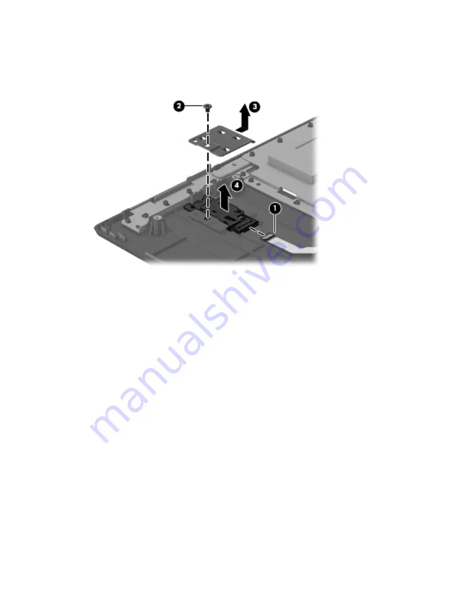
Lift the fingerprint reader bracket up off of its alignment pins and out of its slot in the top cover
(3)
.
4.
The fingerprint reader is held in place with double-sided adhesive. Carefully pry the fingerprint
reader up off of the top cover
(4)
.
Reverse this procedure to install the fingerprint reader board.
Component replacement procedures
53
Содержание 242 G1
Страница 1: ...HP 242 G1 Notebook PC Maintenance and Service Guide ...
Страница 4: ...iv Important Notice about Customer Self Repair Parts ...
Страница 6: ...vi Safety warning notice ...
Страница 26: ...Computer major components Computer major components 17 ...
Страница 58: ...8 Remove the keyboard 3 Reverse this procedure to install the keyboard Component replacement procedures 49 ...
Страница 80: ...2 Remove the speakers 2 Reverse this procedure to install the speakers Component replacement procedures 71 ...


