GB
9
Table of burner and nozzle specifications
Table 1
Liquid Gas
Natural Gas
Diameter
(mm)
Thermal Power
kW (p.c.s.*)
By Pass
1/100
Nozzle
1/100
Flow*
g/h
Nozzle
1/100
Flow*
l/h
Nozzle
1/100
Flow*
l/h
Burner
Nominal
Reduced
(mm) (mm) *** **
(mm) (mm)
Triple
Crown (TC)
309 2x10⁷ 309
Semi Fast
(Medium)(S)
75 1.90 0.4
30 69 138
136 104 181 115 181
Auxiliary
(Small)(A)
51 1.00 0.4 30 50 73
71 78 95 85 95
Supply
Pressures
Nominal (mbar)
Minimum (mbar)
Maximum (mbar)
28-30
20
35
37
25
45
20
17
25
13
6,5
18
*
At 15°C 1013 mbar-dry gas
***
Butane P.C.S. = 49,47 MJ/Kg
** Propane P.C.S. = 50,37 MJ/Kg
Natural P.C.S. = 37,78 MJ/m³
TABLE OF CHARACTERISTSICS
Dimensions
Oven HxWxD
Volume
60 l
Useful
measurements
relating to the oven
compartment
width 42 cm
depth 44 cm
height 17 cm
Burners
may be adapted for use with any type of
gas shown on the data plate, which is
located inside the flap or, after the oven
compartment has been opened, on the
left-hand wall inside the oven.
Voltage and
frequency
see data plate
Energy consumption for Natural
convection – heating mode:
D
Traditional mode;
Declared energy consumption for
Forced convection Class – heating
mode:
X
Baking mode.
This appliance conforms to the following
European Economic Community
directives: 2006/95/EC dated 12/12/06
(Low Voltage) and subsequent
amendments - 2004/108/EC dated
15/12/04 (Electromagnetic
Compatibility) and subsequent
amendments - 93/68/EC dated 22/07/93
and subsequent amendments.
2002/96/EC
2009/142/EC of 30/11/09 (Gas)
1275/2008 (Stand-by/ Off mode)
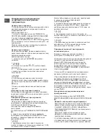
5. Once the adjustment has been made, replace the
seals on the by-passes using sealing wax
!
If the appliance is connected to liquid gas, the
regulation screw must be fastened as tightly as
possible.
!
Once this procedure is finished, replace the old
rating sticker with one indicating the new type of gas
used. Stickers are available from any of our Service
Centres.
!
Should the gas pressure used be different (or vary
slightly) from the recommended pressure, a suitable
pressure regulator must be fitted to the inlet pipe (in
order to comply with current national regulations).
130 3.25 1.50 63
2x65
236 232 2x99
Data plate, is located inside the flap or, after the oven
compartment has been opened, on the left-hand wall
inside the oven.
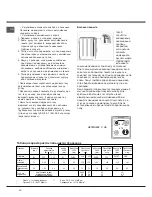
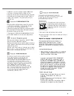
Safety Chain
! In order
to prevent
accidental
tipping of the
appliance, for
example by
a child clim-
bing onto the
oven door, the
supplied safety
chain MUST be
installed!
The cooker is fitted with a safety chain to be fixed by
means of a screw (not supplied with the cooker) to
the wall behind the appliance, at the same height as
the chain is attached to the appliance.
Choose the screw and the screw anchor according
to the type of material of the wall behind the applian-
ce. If the head of the screw has a diameter smaller
than 9mm, a washer should be used. Concrete wall
requires the screw of at least 8mm of diameter, and
60mm of length.
Ensure that the chain is fixed to the rear wall of the
cooker and to the wall, as shown in figure, so that
after installation it is tensioned and parallel to the
ground level.
340x410x424 mm
Regulation (EU) No 65/2014 supplemen-
ting Directive 2010/30/EU.
Regulation (EU) No 66/2014 implementing
Directive 2009/125/EC.
Standard EN 60350-1
Standard EN 50564.
ENERGY LABEL
and ECODESIGN
Standard EN 30-2-1


