58
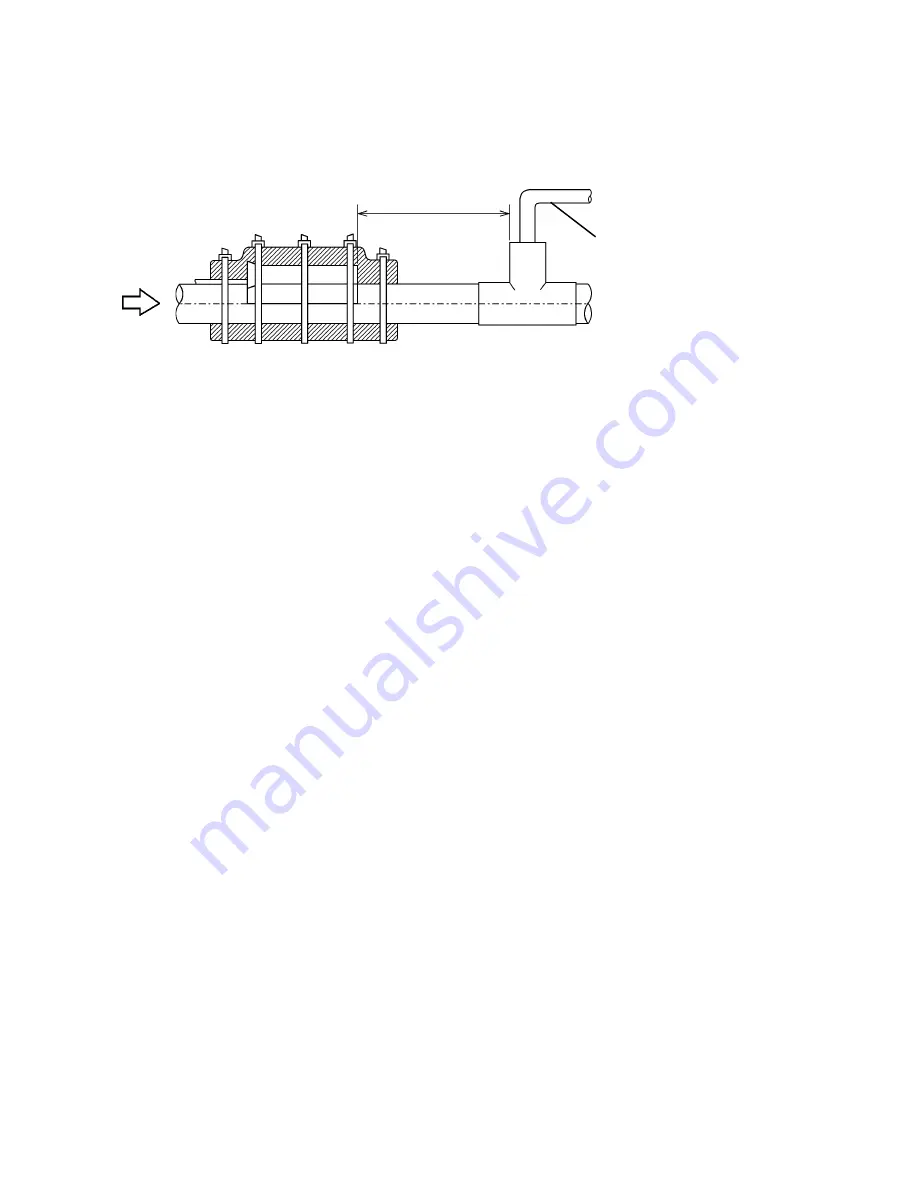
Note: For models with the Liquid Bypass, the Thermistor should be located
upstream from the Liquid Bypass outlet, and its end should be 4-3/4"
or more away from the outlet. See Fig. 3.
Min. 4-3/4"
Liquid Bypass
Flow
10) Secure the insulation using the Plastic Cable Ties.
11) Connect the Thermistor leads through the bushing of the Control Box to the K3
Connector on the Controller Board.
Note: Do not cut the leads of the Thermistor while installing it.
12) Replace the Control Box Cover and the panels in their correct positions.
13) Turn on the power supply.
12. REMOVAL AND REPLACEMENT OF FAN MOTOR
Note: When replacing a Fan Motor with defective winding, it
is recommended that a new capacitor be installed.
1) Turn off the power supply.
2) Remove the panels.
3) Remove the Junction Box Cover from the remote condenser unit (Remote Air-cooled
model).
4) Remove the closed end connectors from the Fan Motor leads.
5) Remove the Fan Motor Bracket and Fan Motor.
Fig. 3
Содержание KM-500MAH
Страница 28: ...28 III TECHNICAL INFORMATION 1 WATER CIRCUIT AND REFRIGERANT CIRCUIT a KM 500MAH ...
Страница 29: ...29 b KM 500MWH ...
Страница 30: ...30 c KM 500MRH ...
Страница 32: ...32 KM 500MAH with auxiliary codes M 2 and after and KM 500MWH with auxiliary codes M 4 and after ...
Страница 34: ...34 b KM 500MRH with auxiliary codes M 2 and after ...
Страница 35: ...35 3 TIMING CHART ...
Страница 36: ...36 ...


