background image

ENGLISH

FRANCAIS

DEUTSCH

IMPORTANT SAFETY INFORMATION ...................................................................................................1

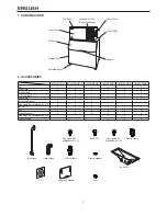
1. CONSTRUCTION ..............................................................................................................................2

2. ACCESSORIES .................................................................................................................................2

3. UNPACKING ......................................................................................................................................3

4. LOCATION .........................................................................................................................................3

5. INSTALLATION ..................................................................................................................................4

6.  STACKING ICEMAKERS ...................................................................................................................5

7.  ELECTRICAL CONNECTIONS ..........................................................................................................6

8.  REMOTE CONDENSER UNIT ...........................................................................................................6

[a] UNPACKING, INSPECTION, PREPARATION .............................................................................6

[b] LOCATION ....................................................................................................................................7

[c] INSTALLATION .............................................................................................................................7

[d] ELECTRICAL CONNECTIONS .....................................................................................................9

[e] STACKING CONDENSER UNITS ................................................................................................9

9.  WATER SUPPLY AND DRAIN CONNECTIONS .............................................................................10

10.  START-UP PROCEDURE ...............................................................................................................11

11.  FINAL CHECKS ...............................................................................................................................12

INFORMATIONS DE SECURITE IMPORTANTES ...............................................................................13

1. CONSTRUCTION ............................................................................................................................14

2. ACCESSOIRES ...............................................................................................................................14

3. DEBALLAGE ....................................................................................................................................15

4. EMPLACEMENT ..............................................................................................................................15

5. INSTALLATION ................................................................................................................................16

6.  EMPILEMENT DE MACHINES A GLACE .......................................................................................17

7.  BRANCHEMENTS ELECTRIQUES .................................................................................................18

8.  UNITE DE CONDENSEUR A DISTANCE .......................................................................................19

[a] DEBALLAGE, INSPECTION, PREPARATION ...........................................................................19

[b] EMPLACEMENT .........................................................................................................................19

[c] INSTALLATION ...........................................................................................................................20

[d] BRANCHEMENTS ELECTRIQUES ............................................................................................21

[e] EMPILEMENT D’UNITES DE CONDENSEUR ...........................................................................22

9.  BRANCHEMENTS D’ARRIVEE ET DE VIDANGE D’EAU ..............................................................22

10.  PROCEDURE DE MISE EN ROUTE ...............................................................................................24

11.  DERNIERS CONTROLES ...............................................................................................................24

WICHTIGE SICHERHEITSHINWEISE ..................................................................................................25

1. KONSTRUKTION .............................................................................................................................26

2. ZUBEHÖR ........................................................................................................................................26

3. AUSPACKEN ...................................................................................................................................27

4. AUFSTELLORT ................................................................................................................................27

5. INSTALLATION ................................................................................................................................28

6.  STAPELN VON EISBEREITERN .....................................................................................................29

7.  ELEKTRISCHE ANSCHLÜSSE .......................................................................................................30

8.  EXTERNE VERFLÜSSIGEREINHEIT .............................................................................................30

[a] AUSPACKEN, PRÜFEN, VORBEREITEN ..................................................................................30

[b] STANDORT .................................................................................................................................31

[c] INSTALLATION ...........................................................................................................................31

[d] ELEKTRISCHER ANSCHLUSS ..................................................................................................33

[e] STAPELN VON VERFLÜSSIGEREINHEITEN ...........................................................................33

9.  WASSERZULAUF- UND WASSERABLAUFANSCHLÜSSE ...........................................................34

10. START-VERFAHREN ......................................................................................................................36

11. ABSCHLUSSTESTS ........................................................................................................................36
Содержание IM-240DNE

Страница 1: ...ANUAL NOTICE D INSTALLATION INSTALLATIONSANLEITUNG INSTALLATIE VOORSCHRIFT MANUAL DE INSTALACION MANUALE PER L INSTALLAZIONE FOR QUALIFIED INSTALLER ONLY RESERVE A L INSTALLATEUR FÜR DEN INSTALLATEUR VOOR DE BEVOEGDE INSTALLATEUR SOLAMENTE PARA INSTALADOR CUALIFICADO SOLTANTO PER INSTALLATORI QUALIFICATI IM 240DNE IM 240XNE IM 240DWNE IM 240XWNE IM 240DSNE IM 240XSNE IM 240DNE C IM 240DWNE C IM 24...

Страница 2: ...MACHINES A GLACE 17 7 BRANCHEMENTS ELECTRIQUES 18 8 UNITE DE CONDENSEUR A DISTANCE 19 a DEBALLAGE INSPECTION PREPARATION 19 b EMPLACEMENT 19 c INSTALLATION 20 d BRANCHEMENTS ELECTRIQUES 21 e EMPILEMENT D UNITES DE CONDENSEUR 22 9 BRANCHEMENTS D ARRIVEE ET DE VIDANGE D EAU 22 10 PROCEDURE DE MISE EN ROUTE 24 11 DERNIERS CONTROLES 24 WICHTIGE SICHERHEITSHINWEISE 25 1 KONSTRUKTION 26 2 ZUBEHÖR 26 3 A...

Страница 3: ... HIELO 53 7 CONEXIONES ELÉCTRICAS 54 8 UNIDAD CONDENSADORA REMOTA 55 a DESEMBALAJE INSPECCIÓN PREPARACIÓN 55 b UBICACIÓN 55 c INSTALACIÓN 56 d CONEXIONES ELÉCTRICAS 57 e ACOPLAMIENTO DE UNIDADES CONDENSADORAS 58 9 SUMINISTRO DE AGUA Y CONEXIONES DE DRENAJE 58 10 PROCEDIMIENTO DE PUESTA EN MARCHA 60 11 COMPROBACIONES FINALES 60 INFORMAZIONI IMPORTANTI SULLA SICUREZZA 61 1 COMPONENTI 62 2 ACCESSORI ...

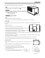
Страница 4: ...nstallation start up the icemaker to check for any abnormalities Instruct the user on how to use and maintain the icemaker in accordance with the instruction manual This booklet should be handed over to the user after the installation and be preserved by the user together with the instruction manual for any further consultation that may be necessary WARNING This is a commercial icemaker and should...

Страница 5: ... 1 Inlet Hose 1 2 1 1 2 2 Outlet Hose 1 2 1 1 2 2 1 2 3 4 Nipple 2 2 2 Ice Chute 1 1 1 Mounting Bracket 2 2 2 Hex Head Bolt w Washers 5 x 12 2 2 2 Bolt 8 x 16 2 2 2 2 2 2 Nut 2 2 2 2 2 2 Plastic Washer 4 4 4 4 4 4 Hex Head Bolt w Washers 4 x 10 4 4 4 Plastic Clamp 2 2 2 Outlet Hose CD Inlet Hose Mounting Bracket 1 2 3 4 Nipple Ice Chute Hex Head Bolt w Washers 4 x 10 Bolt 8 x 16 Plastic Washer Nut...

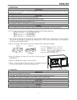
Страница 6: ...nnel See the instruction sheet attached to the storage bin for its unpacking and installation guidelines 2 Remove the icemaker panels to gain access to the accessory kit and to assist easier installation 3 Remove the package of accessories Check the contents according to 2 ACCESSORIES 4 Remove the shipping tape holding the bin control switch 5 Remove the protective plastic film from the exterior I...

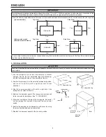
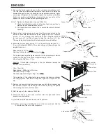
Страница 7: ... Incorrect installation can cause harm to people animals or other items for which the manufacturer cannot be held responsible 1 Lay the storage bin on its rear side carefully to prevent damage Secure the four adjustable legs bin accessory into the four tapped holes on the underside of the bin 2 Position the storage bin in the selected permanent position and level it in both the left to right and f...

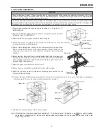
Страница 8: ...e left bottom of the condensing unit and secure it using the two screws and the two washers provided 6 Before stacking disconnect the bin control switch leads with three way plug from the upper or middle unit Remove the screws and the bin control switch When stacking two or three icemakers the switch for the upper unit will not be required Keep it after removal 7 Attach the upper or middle unit on...

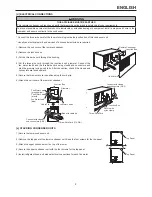
Страница 9: ... the U K and the Republic of Ireland only The wires in the mains lead are coloured in accordance with the following code Green Yellow Earth Blue Neutral Brown Live As the colours of the wire in the mains lead of this appliance may not correspond with the coloured markings identifying the terminals in your plug proceed as follows The wire which is coloured Green and Yellow must be connected to the ...

Страница 10: ...be required Normal condenser ambient temperature 1 C to 40 C Temperatures not within this operating range may affect the production capacity of the icemaker When the condenser unit is installed on a roof a 50 cm height base is recommended to prevent heat reflection and to avoid the possibility of the unit standing in water The maximum line length is 10 m For information on longer line installation...

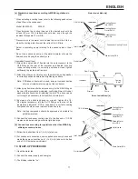
Страница 11: ...e up to 10m 2000g Additional charge for each additional meter 40g As the total precharged refrigerant amount in the icemaker and remote condenser is 2000g the required refrigerant charge will be 40g x length of tube run 10 m Example If the length of tubing run is 15m i e distance between the icemaker and Condenser 15m 10m 5m Base charge 2000g up to 10m run Additional charge 40g m Required refriger...

Страница 12: ...wire cord using closed end connectors and bind the grommet using a cable tie After connection check if the closed end connectors are faced upward 5 Secure the three wire cord in position using the cord grip 6 Attach the unit cover of the remote condenser e STACKING CONDENSER UNITS 1 Secure the lower condenser unit 2 Remove the top panel of the lower condenser unit Keep the four screws for the top ...

Страница 13: ...ance Do not reuse any old hose sets Air Cooled Model 1 Attach the angled end of flexible inlet hose accessory to the G3 4 fitting on the rear of the icemaker as indicated ensuring rubber sealing washer is correctly positioned Hand tighten sufficiently to provide leak free joint 2 Attach the other end of inlet hose to the water tap noting washer is correctly positioned before hand tightening as abo...

Страница 14: ...dicated confirming fitment of rubber washer before finally hand tightening the joint The hose can be cut to length as necessary to suit position of main drain 4 By means of a suitable spanner or wrench tighten the 1 2 3 4 nipples accessory into the Rc1 2 fittings on the rear of the icemaker as indicated P T F E tape and or a suitable sealing compound should be used to obtain a leak free joint Note...

Страница 15: ...n the trial run It might be contaminated with foreign matter in the water circuit Discard or flush down the drain Clean the storage bin before use see III 1 CLEANING in instruction manual 11 FINAL CHECKS 1 Check for correct supply voltage 2 Check that the icemaker is properly earthed 3 Check that the icemaker is free from vibration 4 Check that all the panels are fixed and secure 5 Check for prope...

Страница 16: ...instructions A la fin de l installation mettre la machine à glace en service pour vérifier l absence d anomalies Indiquer à l utilisateur comment utiliser et entretenir la machine à glace conformément à la notice d utilisation Cette notice doit être remise à l utilisateur après l installation et conservée par ce dernier avec la Notice d utilisation pour consultation ultérieure éventuelle AVERTISSE...

Страница 17: ... 2 Mamelon 1 2 3 4 2 2 2 Goulotte de sortie de la glace 1 1 1 Support de fixation 2 2 2 Boulon à tête hexagonale avec rondelles 5 x 12 2 2 2 Boulon 8 x 16 2 2 2 2 2 2 Ecrou 2 2 2 2 2 2 Rondelle en plastique 4 4 4 4 4 4 Boulon à tête hexagonale avec rondelles 4 x 10 4 4 4 Collier en plastique 2 2 2 Tuyau de sortie CD Flexible d arrivée Support de fixation Mamelon 1 2 3 4 Goulotte de sortie de la gl...

Страница 18: ...re appel à un technicien qualifié Voir les instructions de déballage et d installation de la machine qui sont fixées au bac de stockage 2 Retirer les panneaux de la machine à glace afin d accéder au kit d accessoires et pour une installation plus facile 3 Retirer le paquet d accessoires Vérifier le contenu conformément à la section 2 ACCESSOIRES 4 Retirer le ruban d emballage retenant le commutate...

Страница 19: ...mager 5 INSTALLATION ATTENTION Une installation incorrecte de la machine peut avoir des conséquences néfastes sur les personnes les animaux ou d autres choses pour lesquelles le fabricant ne peut être tenu responsable 1 Coucher le bac de stockage sur l arrière en veillant à ne pas l endommager Fixer les quatre pieds réglables accessoires de bac dans les quatre orifices taraudés situés sous le bac ...

Страница 20: ...upports de fixation et les boulons fournis 5 Retirer le ruban d emballage retenant le commutateur de commande de bac sur le bac de vidange Mettre le commutateur de commande de bac sur le cadre situé en bas à gauche de l unité de condenseur et le fixer à l aide des deux vis et des deux rondelles fournies 6 Avant l empilement débrancher les fils du commutateur de commande de bac avec fiche triple de...

Страница 21: ... d entretien Hoshizaki Conformément aux exigences de la norme IEC l impédance maximale admise du système Zmax au point d interface de l alimentation électrique à connecter à cette machine à glace doit être de 0 23 j0 23 ohm S assurer en concertation avec le fournisseur d électricité si nécessaire que la machine à glace est raccordée uniquement à une alimentation de 0 23 j0 23 ohm ou moins Pour le ...

Страница 22: ...eur refroidi par air b EMPLACEMENT Le condenseur est destiné à une utilisation extérieure et doit être placé dans un lieu permanent bien ventilé selon les directives suivantes Choisir un lieu dont la surface est ferme et plane Ne doit pas être exposé à des conditions météo difficiles ou adverses De préférence dans un endroit sec et bien ventilé avec une distance de 60 cm à l avant et à l arrière p...

Страница 23: ...re des soupapes d accès sur la machine à glace Drainer les conduites via les ports de manomètre pendant 20 minutes à 0 1 torr maximum Charger les deux conduites avec du liquide de refroidissement R404A sous forme de vapeur à une pression de 1 bar Ajouter de l azote afin de faire monter la pression à 15 bars Rechercher d éventuelles fuites au niveau des joints à l aide d un détecteur de fuites ou d...

Страница 24: ...ur du boîtier de raccordement de cette unité de condenseur En général l installation nécessite une autorisation pour travaux électriques et les services d un électricien qualifié 1 Retirer les protections de l unité de condenseur à distance 2 Déposer le boîtier de raccordement 3 Faire passer le cordon triple dans la rondelle 4 Faire passer le cordon triple dans le passe fil du boîtier de raccordem...

Страница 25: ...qu il faille obtenir une autorisation pour effectuer les travaux de plomberie et avoir recours aux services d un plombier autorisé La vidange d eau de la machine à glace s effectue par gravité le tuyau de vidange doit donc avoir une inclinaison ou une hauteur de chute suffisantes Les tuyaux de vidange ne doivent pas être reliés directement à l égout L extrémité des tuyaux de vidange de la machine ...

Страница 26: ...s Ne pas utiliser de pompe en cascade car le régulateur d eau modifiera le flux et l arrêtera lors du dégivrage Branchements de la machine à glace 1 Raccorder l extrémité coudée du tuyau d arrivée d eau accessoire au raccord G3 4 à l arrière de la machine à glace comme indiqué en veillant à placer correctement la rondelle d étanchéité en caoutchouc Serrer manuellement de manière à obtenir un racco...

Страница 27: ...e moteur de la pompe démarre g L électrovanne d arrivée d eau se ferme HYGIENE Vérifier les conditions et la qualité de la production de glace Ne pas utiliser la glace produite durant l essai Elle pourrait être contaminée par des impuretés se trouvant dans le circuit d eau La jeter ou la vider dans le circuit de vidange Avant d utiliser la machine nettoyer le bac de stockage voir III 1 NETTOYAGE d...

Страница 28: ...halten Sie nach Abschluss der Installation den Eisbereiter ein und überprüfen Sie ihn auf Unregelmäßigkeiten Weisen Sie den Benutzer in Gebrauch und Instandhaltung des Eisbereiters entsprechend der Bedienungsanleitung ein Diese Broschüre sollte dem Benutzer nach der Installation ausgehändigt und von diesem zusammen mit der Bedienungsanleitung aufbewahrt werden damit bei Bedarf darin nachgelesen we...

Страница 29: ...2 1 1 2 2 1 2 3 4 Stutzen 2 2 2 Eisschacht 1 1 1 Montagehalterung 2 2 2 Sechskantschraube mit Unterlegscheiben 5 x 12 2 2 2 Schraube 8 x 16 2 2 2 2 2 2 Mutter 2 2 2 2 2 2 Kunststoff Unterlegscheibe 4 4 4 4 4 4 Sechskantschraube mit Unterlegscheiben 4 x 10 4 4 4 Kunststoffklammer 2 2 2 Ablaufschlauch CD Zulaufschlauch Montagehalterung 1 2 3 4 Stutzen Eisschacht Sechskantschraube mit Unterlegscheibe...

Страница 30: ...en Siehe Anleitungsblatt am Vorratsbehälter für Richtlinien zum Auspacken und zur Installation 2 Für den Zugang zum Zubehörbausatz und für eine leichtere Installation die Platten des Eisbereiters entfernen 3 Die Packung mit den Zubehörteilen herausnehmen Den Inhalt anhand von 2 ZUBEHÖR kontrollieren 4 Das Transportsicherungsband des Behälterendschalters entfernen 5 Die Kunststoff Folie von der Auß...

Страница 31: ...ne falsche Installation kann zu Verletzungen von Menschen und Tieren oder zu Sachschäden führen für die der Hersteller nicht haftet 1 Den Vorratsbehälter vorsichtig auf die Rückseite legen um Beschädigung zu vermeiden Die vier verstellbaren Gerätefüße Vorratsbehälterzubehör in den vier Gewindebohrungen auf der Unterseite des Vorratsbehälters sichern 2 Den Vorratsbehälter am ausgesuchten permanente...

Страница 32: ...t den zwei mitgelieferten Schrauben und den zugehörigen Unterlegscheiben sichern 6 Vor dem Aufeinanderstapeln die Behälterendschalterkabel mit Dreiwegestecker vom oberen oder mittleren Gerät trennen Die Schrauben und den Behälterendschalter entfernen Beim Stapeln von zwei oder drei Eisbereitern wird der Schalter für die obere Einheit nicht benötigt Nach dem Entfernen aufbewahren 7 Die obere oder m...

Страница 33: ...al 0 23 j0 23 Ohm für den Anschluss des Eisbereiters abzuklären Nur für das Vereinigte Königreich und die Republik Irland Die Drähte im Netzkabel sind nach dem folgenden Farbcode gekennzeichnet Grün Gelb Erde Blau Nullleiter Braun spannungsführender Leiter Die Farben der Adern im Netzkabel dieses Geräts stimmen möglicherweise nicht mit den Farbmarkierungen in Ihrem Stecker überein daher bitte imme...

Страница 34: ...n und flachen Platz wählen Keine rauen oder ungünstigen Wetterbedingungen Vorzugsweise Aufstellung in einem trockenen gut belüfteten Bereich mit 60 cm Abstand an der Vorder und Rückseite um leichtere Wartung und Reparatur zu ermöglichen Normale Verflüssigerumgebungstemperatur 1 C bis 40 C Temperaturen außerhalb dieses Bereichs können die Produktionskapazität des Eisbereiters beeinträchtigen Wird d...

Страница 35: ... gründlich mit einem Leckprüfgerät oder Seifenschaum auf etwaige undichte Stellen prüfen 6 Die Leitungen erneut bei max 0 1 Torr evakuieren Die Leitungen auf 1 2 bar mit dampfförmigem Kältemittel R404A füllen Die tatsächliche Füllmenge wird von der Rohrlänge abhängen Basisfüllung bis zu 10 m 2 000 g Zusätzliche Füllung für jeden weiteren Meter 40 g Da die gesamte vorgefüllte Kältemittelmenge im Ei...

Страница 36: ...chlusskasten entfernen 3 Das dreiadrige Kabel durch die Kabeleinführung führen 4 Das dreiadrige Kabel durch die Kabeltülle des Anschlusskastens füh ren Die Adern des Ventilatormotorkabels und das dreiadrige Kabel mit Quetschverbindern zusammenklemmen und die Kabeltülle mit einem Kabelbinder sichern Nach dem Anschluss prüfen dass die Quetschver binder nach oben gerichtet sind 5 Das dreiadrige Kabel...

Страница 37: ...führen Vom Ablaufschlauchende des Eisbereiters und des Vorratsbehälters sollte mindestens ein 5 cm hoher vertikaler Luftspalt zum Bodenablauf verbleiben Rücklauf in den Vorratsbehälter verhindern Bei wassergekühlten Modellen muss möglicherweise ein Rücklaufschutz im Kühlwasserkreislauf eingebaut werden Immer die mit dem Gerät gelieferte neue Schlauchgarnitur verwenden Keine alten Schlauchgarniture...

Страница 38: ...hrauben Dabei darauf achten dass die Gummidichtung richtig liegt Mit der Hand so anziehen dass die Verbindung dicht ist 2 Das andere Ende des Zulaufschlauchs an den Wasserhahn schrauben dabei wie oben darauf achten dass die Gummidichtung richtig liegt und mit der Hand festziehen Hinweis Falls eine Filtrierung oder Aufbereitung benutzt wird müssen Sie sicherstellen dass nur der Eisbereiterabschnitt...

Страница 39: ...GIENE Prüfen Sie die Bedingungen und die Qualität der Eisherstellung Das Eis aus dem Testlauf nicht verwenden Es könnte durch Fremdstoffe im Wasserkreislauf kontaminiert sein Das Eis wegwerfen oder den Abfluss hinunterspülen Vorratsbehälter vor der Verwendung reinigen siehe III 1 REINIGEN in der Betriebsanleitung 11 ABSCHLUSSTESTS 1 Auf richtige Versorgungsspannung prüfen 2 Prüfen dass der Eisbere...

Страница 40: ...t nadat de installatie is voltooid de ijsmachine op om te controleren op afwijkingen Geef de gebruiker instructies voor het gebruik en onderhoud van de ijsmachine in overeenstemming met de instructiehandleiding Dit boekje moet na de installatie aan de gebruiker worden overhandigd die het bij de gebruiksaanwijzing moet bewaren voor eventueel toekomstig gebruik WAARSCHUWING Dit is een ijsmachine voo...

Страница 41: ... 1 1 2 2 Afvoerslang 1 2 1 1 2 2 1 2 3 4 verloopnippel 2 2 2 Uitvalschacht 1 1 1 Bevestigingsbeugel 2 2 2 Zeskantbout met sluitringen 5 x 12 2 2 2 Bout 8 x 16 2 2 2 2 2 2 Moer 2 2 2 2 2 2 Plastic sluitring 4 4 4 4 4 4 Zeskantbout met sluitringen 4 x 10 4 4 4 Plastic klem 2 2 2 Afvoerslang Cd Toevoerslang Bevestigingsbeugel 1 2 3 4 verloopnippel Uitvalschacht Zeskantbout met sluitringen 4 x 10 Bout...

Страница 42: ... raadpleeg bevoegd servicepersoneel Raadpleeg het instructieblad dat bij de bunker is gevoegd voor richtlijnen bij het uitpakken en installeren 2 Verwijder de panelen van de ijsmachine om toegang te verkrijgen tot het pakket met toebehoren en voor gemakkelijkere installatie 3 Verwijder het pakket met de accessoires Controleer de inhoud aan de hand van 2 TOEBEHOREN 4 Verwijder de transporttape waar...

Страница 43: ...chine niet in een ruimte waar de vloer kan worden aangetast door water 5 INSTALLATIE VOORZICHTIG Onjuiste installatie van de ijsmachine kan schade toebrengen aan mens dier en omgeving De fabrikant aanvaardt geen aansprakelijkheid voor schade en of letsel ten gevolge van het onjuist installeren van de machine 1 Leg de opslagbunker voorzichtig op de achterkant om schade te voorkomen Zet de vier stel...

Страница 44: ...nsor en zet die vast met de twee bijgeleverde schroeven en de twee sluitringen 6 Maak voor het stapelen de verbindingsdraden van de bunker driepensconnector los van het bovenste of middelste apparaat Verwijder de schroeven en de bunkerschakelaar Bij het stapelen van twee of drie ijsmachines is de schakelaar voor de bovenste eenheid niet nodig Gooi de schakelaar niet weg 7 Plaats de bovenste of mid...

Страница 45: ...r zo nodig met behulp van uw elektriciteitsbedrijf dat de ijsmachine wordt aangesloten op een voeding met een systeemimpedantie van 0 23 j0 23 ohm of minder Alleen voor het Verenigd Koninkrijk en Ierland De draden van de netvoeding hebben een kleurcode Groen geel aarde Blauw neutraal Bruin stroomvoerend Als de gekleurde draden in de voedingskabel van deze machine zijn aangesloten op stekkerpolen m...

Страница 46: ...den geplaatst met inachtneming van de volgende richtlijnen Kies een stevige en vlakke ondergrond Mag niet worden blootgesteld aan extreme of ongunstige weersomstandigheden Bij voorkeur op een droge en goed geventileerde plaats met 60 cm vrije ruimte aan de voor en achterzijde zodat eventuele onderhouds en reparatiewerkzaamheden kunnen worden uitgevoerd Normale omgevingstemperatuur van condensor 1 ...

Страница 47: ...leeglopen gedurende 20 minuten bij max 0 1 torr Vul beide leidingen met dampkoelmiddel R404A tot een druk van 1 bar Voeg stikstof toe om de druk tot 15 bar te verhogen Controleer de koppelingen goed met een lekdetector of zeepsop 6 Laat de leidingen weer leeglopen bij max 0 1 torr Vul de leidingen tot 1 2 bar met koelmiddel R404A De werkelijke hoeveelheid is afhankelijk van de lengte van de leidin...

Страница 48: ...platen van de externe condensor 2 Verwijder de aansluitdoos 3 Leid de drieaderige kabel door de doorvoer 4 Leid de drieaderige kabel door de pakkingring van de aansluitdoos Sluit de verbindingsdraden van de ventilatormotor en de drieaderige kabel aan met behulp van connectoren met gesloten uiteinde en bind de pakkingring vast met een kabelbinder Controleer na de aansluiting of de connectoren met g...

Страница 49: ...rlijk verval de afvoerslang moet dus voldoende verval hebben Afvoerleidingen mogen niet rechtstreeks op de riolering worden aangesloten Houd een verticale luchtopening van minimaal 5 cm aan tussen het uiteinde van de afvoerslangen van ijsmachine en bunker en de vloerafvoer Voorkom terugstromen van afvoerwater naar de bunker Bij het watergekoelde model kan het nodig zijn een terugslagklep in het ko...

Страница 50: ... gebogen uiteinde van de flexibele toevoerslang meegeleverd aan de G3 4 aansluiting aan de achterzijde van de ijsmachine zoals weergegeven Let er daarbij op dat de rubber afdichtring goed is aangebracht Voorkom lekkage door de aansluiting handvast aan te draaien 2 Bevestig het andere uiteinde van de toevoerslang aan de waterkraan Zorg ervoor dat de afdichtring goed is aangebracht voordat u de aans...

Страница 51: ...watersysteem sluit HYGIËNE Controleer de kwaliteit van het geproduceerde ijs Het ijs dat tijdens het testen van de ijsmachine is geproduceerd mag niet worden gebruikt voor consumptie Het is mogelijk verontreinigd met deeltjes afkomstig uit het watercircuit Gooi het ijs weg in de afvoer Maak voor ingebruikname van de ijsmachine eerst de bunker schoon zie III 1 SCHOONMAKEN in de instructiehandleidin...

Страница 52: ...ción inicie la máquina de hielo para asegurarse de que está todo correcto Indique al usuario cómo utilizar y mantener la máquina de hielo de acuerdo con el manual de instrucciones Este folleto deberá entregarse al usuario al finalizar la instalación para que lo guarde junto con el manual de instrucciones para cualquier consulta que sea necesaria ADVERTENCIA Esta máquina de hielo comercial solo deb...

Страница 53: ... 1 2 2 Manguera de salida 1 2 1 1 2 2 Boquilla 1 2 3 4 2 2 2 Vertedera del hielo 1 1 1 Soporte de montaje 2 2 2 Tornillo hexagonal con arandelas 5 x 12 2 2 2 Tornillo 8 x 16 2 2 2 2 2 2 Tuerca 2 2 2 2 2 2 Arandela de plástico 4 4 4 4 4 4 Tornillo hexagonal con arandelas 4 x 10 4 4 4 Abrazadera de plástico 2 2 2 Manguera de salida CD Manguera de entrada Soporte de montaje Boquilla 1 2 3 4 Vertedera...

Страница 54: ...ificados Para los procedimientos de instalación y desembalaje véase la hoja de instrucciones que acompaña a la cuba de almacenamiento 2 Desmonte las tapas de la máquina de hielo para acceder al kit de accesorios y proceder a la instalación más fácilmente 3 Retire el embalaje de los accesorios Verifique el contenido de acuerdo con 2 ACCESORIOS 4 Quite la cinta de embalaje que sujeta el interruptor ...

Страница 55: ... el interior de la máquina y gotee en el suelo No la instale en suelos sensibles al agua 5 INSTALACIÓN ATENCIÓN El fabricante no se hace responsable de los daños a personas animales u otros elementos provocados por una instalación incorrecta 1 Tumbe con cuidado la cuba de almacenamiento sobre su parte posterior para evitar dañarla Asegure las cuatro patas ajustables accesorio de la cuba en los cua...

Страница 56: ...tor de control de la cuba a la bandeja de drenaje Acople el interruptor de control de la cuba al marco situado en la parte inferior izquierda de la unidad condensadora y asegúrelo mediante los dos tornillos y las dos arandelas que se proporcionan 6 Antes de acoplarla desconecte los cables del interruptor de control de la cuba con enchufe de tres vías de la unidad superior o media Retire los tornil...

Страница 57: ...rmitida del sistema Zmáx en el punto del interfaz de la alimentación eléctrica que debe conectarse a esta máquina de hielo es de 0 23 j0 23 ohm Después de haberlo consultado con la autoridad pertinente en caso de que sea necesario establezca que la máquina de hielo sea conectada únicamente a un suministro de 0 23 j0 23 ohm o menos Únicamente en el Reino Unido y la República de Irlanda Los hilos de...

Страница 58: ... El condensador está diseñado para su uso exterior y debe colocarse en una ubicación permanente bien ventilada siguiendo las directrices siguientes Seleccione un emplazamiento firme y plano No debe exponerse a condiciones atmosféricas severas o adversas Es preferible un área seca y bien ventilada con un espacio libre de 60 cm en las partes delantera y trasera para facilitar el mantenimiento y serv...

Страница 59: ...emos de cada tubería de cobre para asegurarse de que las conexiones son correctas 3 Los tubos no deben vibrar Sujete o asegure los tubos para evitar la tensión 5 Retire los tapones del puerto del manómetro de servicio desde las válvulas de acceso de la máquina de hielo Vacíe los conductos por los puertos del manómetro durante 20 minutos a un máximo de 0 1 torr Cargue ambos conductos con refrigeran...

Страница 60: ... caja de conexiones de la unidad condensadora Normalmente son necesarios un permiso para obras eléctricas y los servicios de un electricista acreditado 1 Quite la tapa de la unidad condensadora remota 2 Retire la caja de conexiones 3 Pase el cable de tres hilos a través del casquillo 4 Pase el cable de tres hilos a través del pasatubos de la caja de conexiones Conecte los cables del motor del vent...

Страница 61: ...r como máximo Si la presión es superior a 0 8 MPa 8 bar utilice una válvula reductora adecuada NO trate de reducir la presión actuando sobre la llave de paso En algunas localidades pueden ser necesarios un permiso para obras de fontanería y los servicios de un fontanero acreditado El drenaje de la máquina de hielo se realiza por gravedad de modo que la manguera de drenaje debe disponer de la pendi...

Страница 62: ...ule a 4 5 l min Seleccione una bomba de circulación conforme a los valores anteriormente indicados de flujo de calor No utilice una bomba en cascada puesto que el regulador de agua alterará el caudal y lo detendrá durante el ciclo de descongelación Conexiones de la máquina de hielo 1 Una el extremo acodado de la manguera flexible de entrada accesoria al racor G3 4 en la parte posterior de la máqui...

Страница 63: ... de gas caliente cerrada f Bandeja de agua completamente cerrada El motor de la bomba se pone en marcha g La electroválvula del agua se cierra HIGIENE Compruebe el estado y la calidad de la producción de hielo No use el hielo obtenido durante el periodo de prueba Puede estar contaminado con cuerpos extraños del circuito del agua Deseche o lave con agua el drenaje Limpie la cuba de almacenamiento a...

Страница 64: ... Una volta completata l installazione avviare la macchina per verificare che non presenti anomalie Istruire l utente in merito all uso e alla manutenzione della macchina in conformità a quanto riportato nel manuale Il presente manuale deve essere consegnato all utente dopo l installazione perché lo conservi insieme al manuale di istruzioni per eventuali necessità di consultazione AVVERTENZA Questa...

Страница 65: ... Tubo flessibile d uscita 1 2 1 1 2 2 Attacco 1 2 3 4 2 2 2 Scivolo per ghiaccio 1 1 1 Staffa di fissaggio 2 2 2 Bullone a testa esagonale con rondelle 5 x 12 2 2 2 Bullone 8 x 16 2 2 2 2 2 2 Dado 2 2 2 2 2 2 Rondella in plastica 4 4 4 4 4 4 Bullone a testa esagonale con rondelle 4 x 10 4 4 4 Morsetto in plastica 2 2 2 Tubo flessibile d uscita CD Tubo di entrata Staffa di fissaggio Attacco 1 2 3 4...

Страница 66: ...ione si veda il relativo foglio d istruzioni allegato al deposito di raccolta cubetti 2 Smontare i pannelli della macchina per accedere al kit accessori e per agevolare l installazione 3 Rimuovere l imballaggio contenente gli accessori Verificarne il contenuto secondo quanto riportato al punto 2 ACCESSORI 4 Togliere il nastro adesivo che fissa l interruttore di controllo deposito 5 Rimuovere dalla...

Страница 67: ...TTENZIONE L installazione non corretta può provocare lesioni alle persone agli animali e danni materiali per i quali la casa costruttrice declina ogni responsabilità 1 Appoggiare con cura il deposito di raccolta cubetti sul lato posteriore al fine di prevenire eventuali danni Fissare i quattro piedini regolabili in dotazione con il deposito nei quattro fori filettati sul lato inferiore del deposit...

Страница 68: ...parte inferiore sinistra del condensatore e fissarlo servendosi delle due viti e delle due rondelle in dotazione 6 Prima della sovrapposizione scollegare i cavetti dell interruttore di controllo deposito con spina a tre vie dall unità superiore o centrale Togliere le viti e l interruttore di controllo deposito Quando vengono sovrapposte due o tre macchine per l unità superiore non è necessario l i...

Страница 69: ...i fornitura se la macchina è collegata solo a un alimentazione di 0 23 j0 23 ohm o inferiore Solo per il Regno Unito e la Repubblica d Irlanda I fili del cavo di alimentazione sono colorati in base al seguente codice verde e giallo massa blu neutro marrone sotto tensione Dato che i colori dei fili del cavo di alimentazione della macchina possono non corrispondere ai contrassegni colorati che ident...

Страница 70: ...i atmosferiche rigide o avverse È preferibile una zona secca e ben ventilata con uno spazio libero di 60 cm sia sul lato anteriore che sul retro in modo da favorire le eventuali operazioni di manutenzione o servizio Normale temperatura ambiente per il condensatore fra 1 C e 40 C Le temperature non comprese entro questa gamma operativa potrebbero condizionare la capacità di produzione della macchin...

Страница 71: ... di 0 1 torr Caricare le linee a una pressione di 1 2 bar con il refrigerante R404A La carica effettiva dipende dalla lunghezza del tubo Carica base fino a 10 m 2 000 g Carica supplementare per ciascun metro aggiuntivo 40 g La quantità totale di refrigerante caricato precedentemente nella macchina e nel condensatore remoto è 2 000 g Pertanto è necessario caricare una quantità di refrigerante pari ...

Страница 72: ...Inserire il cavo a tre vie attraverso la guarnizione della scatola di giunzione Collegare i cavi del motorino della ventola e il cavo a tre vie mediante dei connettori di coda e vincolare la guarnizione con una fascetta stringicavo Dopo aver effettuato i collegamenti assicurarsi che i connettori di coda siano rivolti verso l alto 5 Fissare il cavo a tre vie con il pressacavi 6 Rimontare la copertu...

Страница 73: ...enaggio a gravità assicurarsi che il tubo di scarico abbia una pendenza adatta I circuiti di scarico non devono essere installati direttamente nella rete fognaria È necessario lasciare un traferro verticale di minimo 5 cm ttra l estremità dei tubi di scarico dalla macchina e il deposito di raccolta cubetti e lo scarico a pavimento Prevenire un riflusso nel deposito di raccolta cubetti Nei modelli ...

Страница 74: ... estremità a gomito del tubo di entrata flessibile accessorio al raccordo G3 4 situato sul retro della macchina come indicato facendo attenzione che la rondella di tenuta in gomma sia posizionata in modo corretto Serrare a mano quanto basta a evitare perdite 2 Collegare al rubinetto dell acqua l altra estremità del tubo flessibile di entrata facendo attenzione che la rondella sia posizionata corre...

Страница 75: ...one di cubetti Non utilizzare i cubetti prodotti durante il ciclo di prova Potrebbero essere contaminati da sostanze estranee presenti nel circuito dell acqua Eliminarli o farli scendere nello scarico Pulire il deposito di raccolta cubetti prima dell uso vedi III 1 PULIZIA nel Manuale di istruzioni 11 CONTROLLI FINALI 1 Verificare la corretta tensione di alimentazione 2 Verificare che la macchina ...

Страница 76: ...后 应将本说明书移交给用户 并由用户妥善保管本说明书和使用说明 书 以便必要时参考使用 生产商 Hoshizaki Europe Ltd Telford 70 Stafford Park 7 Telford Shropshire TF3 3BQ England 联系人 星崎冷热机械 上海 有限公司 上海市静安区南京西路580号 南证大厦2802室 200041 电话 021 5228 8181 传真 021 5228 0113 IM 240DNE IM 240XNE IM 240DWNE IM 240XWNE IM 240DSNE IM 240XSNE IM 240DNE C IM 240DWNE C L2E1CK201 093014 IM 240DNE ...

Страница 77: ...重要安全须知 1 1 构造 2 2 附件 2 4 位置 3 5 安装 4 6 叠放制冰机 5 7 电气连接 5 8 远置冷凝机组 6 9 供水和排水连接 9 10 启动步骤 11 11 最终确认事项 11 ...

Страница 78: ... 小心 表示如不避免 则可能导致轻微受伤或中度受伤的危险情况 注意 表示如不避免 则可能导致本设备损坏的危险情况 卫生 表示与卫生和食品安全相关的重要预防措施 重要 表示与使用和维护本设备相关的重要信息 警告 本制冰机为商用设备 仅适用于该设备所明确设计的用途 且仅可安装到星崎规定的合适的储冰箱上 其它任何用途都被视为不当用途 因而可能造成危险 对因本产品使用不当 使用不正确和不合理所造成的的任何损失 生产 商不承担法律责任或相关责任 安装及必要时的移机作业 必须交由具备相应知识的作业人员依照现行法规并根据生产商的说明进行 保持机体内外通风口畅通无阻 ...

Страница 79: ...IM 240XSNE 光盘 1 1 1 1 1 1 进水软管 1 2 1 1 2 2 排水软管 1 2 1 1 2 2 1 2 3 4螺纹接头 2 2 2 冰槽 1 1 1 安装支架 2 2 2 带垫圈六角头螺栓5 12 2 2 2 螺栓8 16 2 2 2 2 2 2 螺母 2 2 2 2 2 2 塑料垫圈 4 4 4 4 4 4 带垫圈六角头螺栓4 10 4 4 4 塑料线夹 2 2 2 3 拆包 警告 包装零件 塑料袋和发泡聚苯乙烯等 存在潜在危险 必须放置到儿童接触不到的地方 排水软管 光盘 进水软管 安装支架 1 2 3 4螺纹接头 冰槽 带垫圈六角头螺栓 4 10 螺栓8 16 塑料垫圈 螺母 塑料线夹 带垫圈六角头螺栓 5 12 ...

Страница 80: ...后 请检查并确认制冰机和储冰箱状态完好 如有任何疑问 请勿使用本产品 而应与具备相应资质的专业人员联 系 有关拆包和安装指示 请参见储冰箱附带的使用说明 2 拆下制冰机面板 以便于触及附件套件和简化安装 3 打开包装的附件 参照 2 附件 检查附件 4 撕掉固定储冰控制开关的运输用胶带 5 撕掉外表面的塑料防护膜 如果制冰机暴露于阳光下或热源下 请待制冰机冷 却后再撕掉塑料防护膜 4 位置 警告 本制冰机不适合在户外使用 不得将制冰机安装在靠近火炉 烤箱或其它会产生高温的设备附近 本产品不适合安装在可能使用喷水器的区域 小心 制冰机应安装在坚实 平坦的地面上 注意 请勿在制冰机上方或通风窗前方放置任何物品 重要 正常工作的环境温度应为1 40 供水管路只可连接冷水 如果制冰机长时间超出上述正常温度范围工作 可能会影响制冰 能力 a 前盖板 拆下螺钉 将前盖板上提并向外拉动 b 顶板 拆下螺...

Страница 81: ...制冰机 高湿度环境下 机器内部可能会产生冷凝水 从而滴在地上 因此 请勿将其安装在易受滴水影响的地板上 5 安装 小心 错误的安装会导致人员 动物受伤或其它物品受损 生产商对由此造成的损害不承担责任 1 请将储冰箱以背面着地放于地上 以防损坏 然后将四个可调节支脚 储冰箱附件 拧入储冰箱底部的四个锥形孔中 2 将储冰箱放置在固定的位置 使其在前后和左右方向上均保持水平 3 使用储冰箱左侧或右侧附带的螺钉安装顶部套件 4 拆下制冰机面板 后面板在安装作业过程中无需拆下 请参见 3 拆包 5 将制冰机置于储冰箱的顶部 小心操作 以免损坏制冰机边框和储冰控制开关 6 使用附带的安装托架和螺栓 从后面将制冰机固定至储冰箱上 7 将制冰机面板装回原位 底部 可调节支脚 可调节支脚 顶部套件 制冰机 安装支架 螺栓 储冰箱 螺栓 安装支架 ...

Страница 82: ...冷凝机组 左下方的边框上 然后使用附带的两个螺钉和两个垫圈进行紧固 6 叠放制冰机前 请从上部或中部制冰机上断开储冰控制开关导线 带三芯插头 然后 拆下螺钉和储冰控制开关 当叠放两台或三台制冰机时 无需留用上部制冰机的开 关 请妥善保管拆下的开关 7 将上部或中部制冰机置于下部制冰机上方 8 使用附带的两个螺栓和螺母紧固两台制冰机 9 安放冰槽 中部或下部制冰机附件 并使用两个螺钉将其固定至托架上 10 将位于下部制冰机布线槽中的导线 带三芯插头 连接到上部或中部制冰机的插座中 已在上述步骤6中断开 然后使用附带的塑料线夹固定导线 11 将制冰机面板装回原位 注 若要堆叠三台制冰机 则请按照步骤6 11 对上部制冰机进行操作 但请记住 无论如何配置 只需一个储冰控制开关即 可 储冰控制开关的延长导线已预先压接至插头 并盘绕在X型制冰机的布线槽中 7 电气连接 警告 本制冰机必须接地 本制冰...

Страница 83: ...需要如下所示的推荐零部件和材料 线 制 冰 机 和 冷 凝 机 组 之 间 L N 的 风 扇 马 达 配 线 需 要 使 用 线 径 为 17AWG 1 0mm2 的三芯线 铜管 磷脱氧铜管 冷媒管路需要管径相同的两根铜管 请在用于气体管路和液体 管路的铜管上绘制清晰的识别标记 以防接错 9 52 外径 7 93 内径 气体 9 52 外径 7 93 内径 液体 配管隔热材料 用于气体和液体配管 需具备最高120 的耐热能力 螺栓 用于紧固冷凝机组的4个M8六角螺栓 5 完成安装前 请勿拆下机组盖板 以防损坏风冷型冷凝机组 b 位置 本冷凝机组适合在室外使用 必须按照下列规定将其置于通风始终良好的地方 请选择一处坚实 平坦的安装位置 应避免将其安装在气候条件恶劣的地方 最好将其安装在干爽且通风良好的地方 并在前后侧各留出60cm的空间 以便于维 修保养 正常冷凝环境温度为 1 40 若超...

Страница 84: ... 以防产生 应力 5 首先拆下制冰机充灌阀上的检测仪表端口盖 并在最大压力为 0 1torr的条件下通过该端口对管路进行20分钟的抽真空操作 然 后 在向两条管路中充填气态冷媒R404A并使压力达到1bar后 继 续追加充填氮气 以使压力升高至15bar 最后 利用检漏器或肥 皂泡全面检测各个接头处的泄漏情况 6 首先 在最大压力为0 1torr条件下重新对管路进行抽真空操作 向 管路中充填气态冷媒R404A 使压力达到1 2bar 实际充填量视 管长而定 不超过10m管长时的基本充填量 2000g 每延长1m管长所需的追加充填量 40g 由于制冰机和远置式冷凝机组中预充填冷媒总量为2000g 因此所 需充填的冷媒量为 40g 管长 10 m 例如 若管长为15m 即制冰机和冷凝机组之间的距离 15m 10m 5m 基本充填量 2000g 不超过10m管长时 追加充填量 40g m 所需充...

Страница 85: ...气安全标准进行接地 为避免造成人体触电或设备严重受损 请在制冰机上正确地连接地线并确保其与冷凝机组的导通性良好 请连接本冷凝机组接线盒内的三芯风扇马达配线 通常情况下 应由持有电工资质证书或经授权的维修人员进行作业 1 拆下远置式冷凝机组盖板 2 拆下接线盒 3 将三芯线从套筒中穿过 4 将三芯线从接线盒的索环中穿过 使用闭端端子连接风扇马达导线和三芯 线并使用扎带固定好索环 完成连接后 请检查闭端端子是否朝上 5 使用压线扣将三芯线固定 6 将远置式冷凝机组盖板装回原位 液体管路 气体管路 配管隔热材料 三芯线 压线扣 充灌阀 平直面 充灌阀 机组盖板 远置式冷凝机组 接线盒 接线盒 索环 风扇马达导线 电缆扎带 风扇马达导线 绿色 黄色 风扇马达导线 黑色 风扇马达导线 蓝色 利用扎带进行固定 三芯线 17AWG 利用闭端端子 CE 2 进行连接 利用闭端端子 CE 2 进行连接 接线...

Страница 86: ...r 之间 如果水压超过0 8MPa 8bar 则须采用适当的减压阀 请勿关小供水龙头 在部分地区可能要求具备水管敷设许可证并由持有相应资质证书的水管工进行作业 制冰机排水靠重力流动 因此应保证排水软管具有足够的坡度或落差 不得将排水管路直接连接至下水道系统 制冰机和储冰箱的排水软管末端与地面排水之间至少需留 出5cm的垂直空隙 应防止排水回流至储冰箱内 对于水冷机型 可能需要在冷却水路中安装一个防回流阀 请务必使用本机附带的全新软管套件 请勿使用老旧的软管套件 风冷机型 1 如图所示 将挠性进水软管 附件 的弯角端连接到制冰机后部的G3 4管接头上 并确认橡胶密封垫圈已正确就位 手动充分拧 紧垫圈 以防止接头漏水 2 将进水软管的另一端连接到供水龙头 并在如上所述手动拧紧前检查垫圈是否正确就位 最好在易于触及的部位安装一个截 止阀 3 如图所示 将灰色挠性排水软管 附件 手动紧固至制冰机后...

Страница 87: ...动充分拧紧垫圈 以防止接头漏水 2 将进水软管的另一端连接到供水龙头 并在如上所述手动 拧紧前检查垫圈是否正确就位 注 如果使用了过滤或水处理装置 应确保仅将处理水供 水源连接至制冰机部分 而非冷凝器 3 如图所示 将灰色挠性排水软管 附件 连接到制冰机后部的 R3 4管接头上 并在最终手动拧紧接头前确认橡胶垫圈已 正确就位 可根据主排水口的位置将排水软管剪切到合适 的长度 4 如图所示 使用合适的扳手或扳钳将1 2 3 4螺纹接头 附 件 紧固至制冰机后方的Rc1 2管接头中 并使用P T F E 胶 带和 或合适的密封剂密封 以防止接头漏水 注 接头密封剂必须经过有关部门批准并符合饮用水 标准 5 如图所示 使用合适的刚性管将冷凝器冷却水路连接至 1 2 3 4螺纹接头的自由端 b 使用各种软管附件根据WRAS之外的规定进行的连接 1 根据上文 a 中的步骤1 4 进行操作 2 如图所...

Страница 88: ...水盘将完全打开 d 进水电磁阀将打开 e 接水盘将开始闭合 热气阀关闭 f 接水盘完全闭合 水泵马达将起动 g 进水电磁阀将关闭 卫生 检查制冰情况和质量 请勿使用在试运行过程中制成的冰块 因为水路中可能含有水垢 二氧化硅 氧化钙或其它异物 请丢弃或冲走排水 使用前须清洁储冰箱 参见使用说明书中的 III 1 清洁 11 最终确认事项 1 检查电压是否正常 2 检查制冰机接地是否正确 3 检查制冰机是否存在振动 4 检查所有面板是否均已安装牢固 5 根据 10 启动步骤 检查运行是否正常 6 检查供水及排水连接处是否漏水 7 指导用户正确操作本机 并将操作说明书交付给用户 ...

Отзывы: