10
B
D
C
4
4
7
2
A
1
3
C
D
B
A
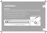
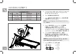
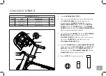
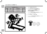
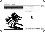
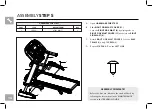
ASSEMBLY
STEP 1
A
Cut the yellow banding straps and lift the running deck
upward from the rear to remove all contents from
underneath the running deck.
B
Open
HARDWARE FOR STEP 1.
C
Insert
UPRIGHT GUIDE BOLT (A)
into
MAIN FRAME
BRACKET (1)
and fully tighten.
D
Attach
LEAD WIRE
to bottom end of
CONSOLE
CABLE (2).
Pull
LEAD WIRE
through R
IGHT
CONSOLE MAST (4)
. After pulling the lead wire
through the mast, the top of the
CONSOLE CABLE (2)
should be located at the
ATTACHMENT BRACKET (7)
.
E
Attach
RIGHT CONSOLE MAST (4)
to
MAIN
FRAME (3)
using
4 BOLTS (B), 4 FLAT WASHERS (C)
AND 4 SPRING WASHERS (D).
Feed the extra console
cable back into the upright mast.
F
Repeat
STEP E
on the
LEFT SIDE
.
M8X1.25PX11L
2
A
UPRIGHT GUIDE BOLT
A
NOTE:
Do not fully tighten the following bolts until the
end of
STEP 4.
B
C
D
HARDWARE FOR STEP 1
PART
TYPE
DESCRIPTION
QTY
M8X1.25PX80L
8
B
MAST BOLT
8.2X15.4X2.0T
8
C
SPRING WASHER
8.4X15.5X1.6T
8
D
FLAT WASHER
NOTE:
Be careful not to pinch the console cable
while attaching the right console mast.
Содержание 7.8 AT
Страница 2: ...2 3 ENGLISH 32 FRAN AIS 62 ESPA OL...
Страница 16: ...16 K T U I J R M M L V V H S...
Страница 29: ...29 LIMITED HOME USE WARRANTY...
Страница 32: ...32 FRAN AIS...
Страница 46: ...46 K T U I J R M M L V V H S...
Страница 59: ...59 GARANTIE LIMIT E D UTILISATION DOMICILE...
Страница 62: ...62 ESPA OL...
Страница 76: ...76 K T U I J R M M L V V H S...
Страница 89: ...89 GARANT A LIMITADA AL USO DOM STICO...


