


#078734DE-EN e
15
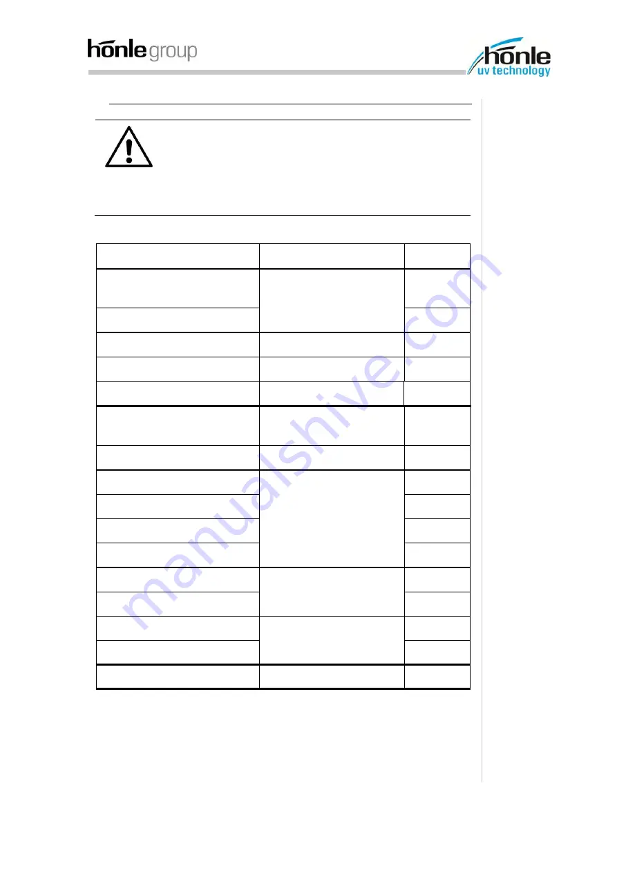
4.4. Activation of control signals
ATTENTION! Material damage!
It may cause damage to the device or the connection ca-
bles, if no higher current strength is ensured.
To avoid this turn the associated PINs of the supply connec-
tions in parallel.
The cross section of the connecting cables is to be dimen-
sioned accordingly to the maximum current (see type plate).
Pin assignment LED powerline AC/IC 410 (15-pin connector)
Function
Description
PIN
Supply voltage
U
b+
= 45V - 55V
Power connection
(I
max
electrical values page 23)
1
Supply voltage GND
15
PLC ON
Input LED ON
2
PLC GND
GND for PLC
6
PLC LEDenable
Input LEDenable
13
analog set point SW +
set point
0
– 10V
≙
0
– 100%
10
analog set point SW -
GND for set point
15
PLC Out OK
status signal of the LED
7
PLC Out ON
9
PLC Out OFF
14
PLC Out COM
8
TxD +
Transmit Data
11
TxD -
3
RxD +
Receive Data
4
RxD -
12
PWM
Fan control
5
Control signals