


VR8215S,T SINGLE STAGE VR8215Q,N TWO STAGE DIRECT IGNITION GAS CONTROLS
69-2253—07
4
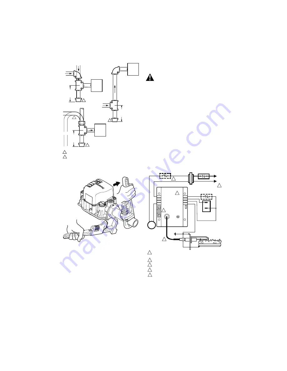
Fig. 2. Sediment trap installation.
Fig. 3. Proper use of wrench on gas control.
Wiring
Follow the wiring instructions furnished by the
appliance manufacturer, if available, or use the
general instructions provided below. When these
instructions differ from the appliance manufacturer,
follow the appliance manufacturer instructions.
IMPORTANT
All wiring must comply with applicable electri-
cal codes and ordinances.
WARNING
Electrical Shock Hazard or Equipment
Damage Hazard.
Can cause serious injury, death or equipment
damage.
Disconnect power supply before making wiring
connections to prevent electrical shock or
equipment damage.
1.
Check the power supply rating on the gas control
and make sure it matches the available supply.
Install a transformer and other controls as
required.
2.
Connect the control circuit to the gas control
terminals. See Fig. 4 and 5.
3.
Two stage gas valve wiring:
MV
- Main valve or low fire.
C
- Common terminal of ignition coils.
HI
- Second stage or high fire.
4.
For single stage controls (VR8215S,T):
adjust thermostat heat anticipator to 0.50A
rating stamped on valve label.
For two stage controls (VR8215Q,N):
adjust thermostat heat anticipator to 0.90A
rating stamped on valve label.
Fig. 4. Typical wiring connections for 24 volt
control in S87 Direct Ignition System.
GAS
CONTROL
GAS
CONTROL
HORIZONTAL
DROP
PIPED
GAS
SUPPLY
PIPED
GAS
SUPPLY
3 IN.
(76 MM)
MINIMUM
3 IN.
(76 MM)
MINIMUM
RISER
GAS
CONTROL
TUBING
GAS
SUPPLY
HORIZONTAL
DROP
3 IN.
(76 MM)
MINIMUM
RISER
M3077
2
1
2
2
1
2
ALL BENDS IN METALLIC TUBING SHOULD BE SMOOTH.
CAUTION: SHUT OFF THE MAIN GAS SUPPLY BEFORE REMOVING
END CAP TO PREVENT GAS FROM FILLING THE WORK AREA. TEST
FOR GAS LEAKAGE WHEN INSTALLATION IS COMPLETE.
M27669
24V
24V (GND)
S87B CONTROL MODULE
ALARM
VALVE
VALVE
GND
TEMPERATURE
CONTROLLER
POWER SUPPLY. PROVIDE DISCONNECT MEANS AND OVERLOAD
PROTECTION AS REQUIRED.
ALTERNATE LIMIT CONTROLLER LOCATION.
MAXIMUM IGNITER-SENSOR CABLE LENGTH: 3 ft. (0.9 m) OR LESS.
3A REPLACEABLE FUSE.
ALARM TERMINAL PROVIDED ON SOME MODELS.
M27697
L1
(HOT)
L2
1
2
1
2
3
DUAL VALVE
COMBINATION
GAS CONTROL
Q347 IGNITER-SENSOR
BURNER
4
4
5
IGNITER-SENSOR AND
BURNER GROUND
3
5
ALARM, IF USED