Honeywell V5004T Скачать руководство пользователя страница 2

V5004TF ACTUATOR – INSTALLATION INSTRUCTIONS 

MU1B-0655GE51 R1019A 

2

3. 

Turn the key while continuing to push down the 
"release" button located on the bottom of the actuator. 

1

2


Fig. 1. Manual override M5004 


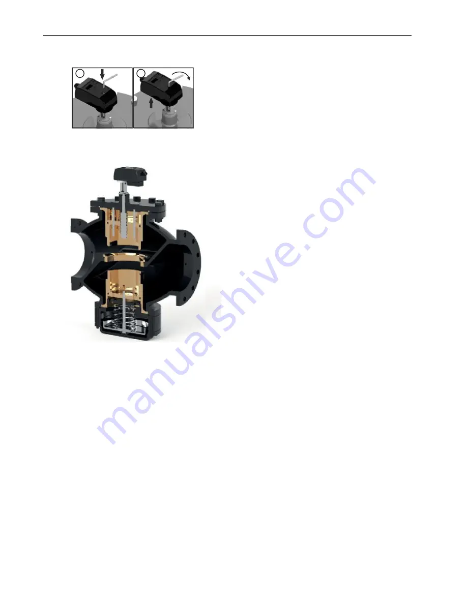
4b. Valve-Actuator Assembly 


Fig. 2. Valve-actuator assembly 


Содержание V5004T

Страница 1: ...mmissioned actuator Proportional flow control Analog voltage and current floating and ON OFF Position feedback 4 digit display 3 buttons to set parameters Position control method to set the flow rate INSTALLATION INSTRUCTIONS 1 Mount the valve with the arrow in the direction of the flow CAUTION Mounting the valve in the wrong direction may damage the system and the valve itself If flow reversal is...

Страница 2: ...ON INSTRUCTIONS MU1B 0655GE51 R1019A 2 3 Turn the key while continuing to push down the release button located on the bottom of the actuator 1 2 Fig 1 Manual override M5004 4b Valve Actuator Assembly Fig 2 Valve actuator assembly ...

Страница 3: ...ing Table 2 Wire guidelines Input Number 1 2 3 4 5 Remarks Color Black BK Red RD White WH Green GN Blue BU Internal control A Common 24 AC DC Feedback 0 2 10 V 0 4 20 mA Power cable 1 2 Voltage signal Common 24 AC DC 0 10 VDC 2 10 VDC Feedback 0 2 10 V 0 4 20 mA Power cable 1 2 Voltage signal cable 1 3 Current signal Common 24 AC DC 0 20 mA 4 20 mA Feedback 0 2 10 V 0 4 20 mA Power cable 1 2 Curre...

Страница 4: ... to perform this task more frequently 6e Dismounting the Actuator To dismount the actuator proceed as follows Turn the connection ring between the valve and the actuator and remove the actuator 1 2 Fig 5 Dismounting the actuator NOTE To avoid damage due to condensation from the valve stem be sure that the actuator is not mounted upside down Please note that care must be taken when installing the a...

Страница 5: ... OFF 24 V open 0 V close Floating input 24 V open if white wire 3 connected 24 V close if green wire 4 connected Remote control Not available PWM 5 sec PWM 0 1 5 sec PWM 25 sec PWM 0 1 25 sec Internal input Flow rate set by onboard display and buttons Push MODE button wait until SET is replaced by flow rate indication or flow rate depending upon S 01 set the flow rate using the UP DOWN buttons and...

Страница 6: ...splay is shown Value on display flow rate offset default 0 Select using the UP DOWN buttons and then press the MODE button to confirm Power failure mode not available Unit of SI m3 h Select using the UP DOWN buttons and then press the MODE button to confirm Unit of GPM gal min Linear control curve Select using the UP DOWN buttons and then press the MODE button to confirm Equal percentage control c...

Страница 7: ...rameter should be set to a value between the valve s max and the min presetting flow rates S 03 should be left at 0 RATIO OF VALUE OF FLOW ACCORDING TO FLOW CURVE Table 5 Ratio of value of flow according to flow curve POSITION of VALVE LIFT unit 0 5 10 15 20 25 30 35 40 45 50 55 60 65 70 75 80 85 90 95 100 LINEAR CURVE unit 0 5 10 15 20 25 30 35 40 45 50 55 60 65 70 75 80 85 90 95 100 EQUAL PERCEN...

Страница 8: ... non condensing Storage temp range 20 80 C non condensing Specifications Weight 0 975 kg Power supply 24 VAC DC 50 60 Hz Power consumption 5 W 2 5 W stand by Connecting cable length 0 25 m Connection to valve 8 mm square Easy fitting gear Operating life 50 000 cycles Control signal 0 2 10 V 250 kΩ burden 0 4 20 mA 500 Ω burden ON OFF 24 VAC DC 30 mA AC 6 mA DC 3 point floating 24 VAC DC 30 mA AC 6...

Страница 9: ...til beschädigen Honeywell lehnt jegliche Haftung für die unsachgemäße oder fehlerhafte Nutzung dieses Produktes ab MERKMALE Betriebsbereiter Stellantrieb Proportionale Steuerung Analoge Spannung und Strom 3 Punkt und AUF ZU Stellsignaleingang Positionsrückmeldung 4 stelliges Display 3 Tasten zur Parametereinstellung Positionssteuerungsmethode zum Einstellen des Durchflusses INSTALLATIONSANWEISUNG ...

Страница 10: ...kel auf der Oberseite des Stallantriebs und stecken Sie den 6 mm Inbussschlüssel ein 3 Drehen Sie den Schlüssel und halten Sie dabei den entsicherten Knopf unter dem Stellantrieb gedrückt 1 2 Abb 1 Manuelle Übersteuerung M5004 4b Ventil Stellantrieb Baugruppe Abb 2 Ventil Stellantrieb Baugruppe ...

Страница 11: ...inien Eingangswert Nr 1 2 3 4 5 Anmerkungen Farbe Schwarz BK Rot RD Weiß WH Grün GN Blau BU Interne Kontrolle A Masse 24 AC DC Rückmeldung 0 2 10 V 0 4 20 mA Leistung Kabel 1 2 Spannungssignal Masse 24 AC DC 0 10 VDC 2 10 VDC Rückmeldung 0 2 10 V 0 4 20 mA Leistung Kabel 1 2 Spannungssignal Kabel 1 3 Stromsignal Masse 24 AC DC 0 20 mA 4 20 mA Rückmeldung 0 2 10 V 0 4 20 mA Leistung Kabel 1 2 Strom...

Страница 12: ...n in der Regel einmal jährlich bzw nach 5 000 Zyklen Unter bestimmten Umwelt und Betriebsbedingungen könnte es nötig sein diese Reinigung öfter durchzuführen 6e Demontage des Stellantriebs Wenn der Stellantrieb demontiert werden muß gehen Sie wie folgt vor Drehen Sie den Verbindungsring zwischen Ventil und Stellantrieb und demontieren Sie den Stellantrieb 1 2 Abb 5 Demontage des Stellantriebs HINW...

Страница 13: ...geschlossen 3 Punkt Eingang 24 V offen wenn weißer Draht 3 angeschlossen ist 24 V geschlossen wenn grüner Draht 4 angeschlossen ist Fernsteuerung Nicht verfügbar PWM 5 Sek PWM 0 1 5 Sek PWM 25 Sek PWM 0 1 25 Sek Festsollwert Volumenstrom eingestellt über On board Display und Tasten Modustaste drücken warten bis Set durch Anzeige des Volumenstroms ersetzt wird oder Volumenstrom je nach S 01 Volumen...

Страница 14: ... angezeigt ist Wert auf dem Display des Volumenstrom Offsets Vorgabe 0 Auswählen mit der Nach oben Nach unten Taste und Bestätigung mit der Modustaste Versorgungsunterbrechungsmodus nicht erhältlich SI Einheit m3 h Auswählen mit der Nach oben Nach unten Taste und Bestätigung mit der Modustaste GPM Einheit gal min Lineare Kennlinie Auswählen mit der Nach oben Nach unten Taste und Bestätigung mit de...

Страница 15: ... max und dem min Voreinstellungs Volumenstroms des Ventils liegen S 03 sollte auf 0 eingestellt bleiben VERHÄLTNIS DES VOLUMENSTROMWERTS GEMÄSS VOLUMENSTROMKENNLINIE Tabelle 5 Verhältnis des Volumenstromwerts gemäß Volumenstromkennlinie POSITION der VENTILÖFFNUNG Einheit 0 5 10 15 20 25 30 35 40 45 50 55 60 65 70 75 80 85 90 95 100 LINEARE KENNLINIE Einheit 0 5 10 15 20 25 30 35 40 45 50 55 60 65 ...

Страница 16: ...gertemperatur 20 80 C nicht kondensierend Spezifikationen Gewicht 0 975 kg Spannungsversorgung 24 VAC DC 50 60 Hz Stromaufnahme 5 W 2 5 W Standby Betrieb Verbindungskabel Länge 0 25 m Verbindung zum Ventil 8 mm Vierkant Einfache Montageausrüstung Betriebsdauer 50 000 Zyklen Stellsignal 0 2 10 V 250 kΩ Last 0 4 20 mA 500 Ω Last AUF ZU 24 VAC DC 30 mA AC 6 mA DC 3 Pkt Steuerung 24 VAC DC 30 mA AC 6 ...

Отзывы: