Honeywell UDC2000 Скачать руководство пользователя страница 3

the Controller for 

Damage 

Carefully inspect your controller as soon as it arrives. 

If it is damaged, call your dealer. Then notify the freight 
agent at  once and  request  an inspection. Save all pack­
ing  materials  for  inspection  by  the  freight  claims  ad­

juster.  Refer to your  packing list for more information. 
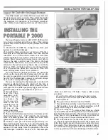
INSTALLING THE 

PORTABLE P 2000 

If you purchased a furnace with a UDC 

2000 

control­

ler  already  installed,  skip  this  section.  This  section 
applies only to the P 

2000, 

which is a portable UDC 

2000 

controller. 

1. 

Position  the  P 

2000 

far  enough  away  from  your 

furnace  to avoid heat  damage. 

2. 

Install the thermocouple on your furnace. (The ther­

mocouple  is  the  temperature-sensor  rod  with  ceramic 

insulators  on  it.)  First,  decide  which  vent  hole  (also 

called  peephole)  to  use.  Find  a 

112" 

vent  hole  on  your 

furnace.  Most  four-sided  furnaces  have  a  vent  hole  in 

the  top,  the  door,  and  the  back.  The  hole  in  the  back 

would  be  the  best  choice,  but  you  could  use  any of  the 

others, too.  If your furnace, by chance, has no vent hole, 
drill one.  Drill  a 

112 

hole  in either a row of blank bricks 

or  at  the  seam  line  where  two  rows  meet.  (This  is  to 
avoid drilling closer than 

1" 

to an element.) 

If  your  furnace  or  kiln  has  two  holes,  one  above the 

other, use the top hole for the thermocouple. If your kiln 
has  only  one  peephole,  you will  need  to drill a  separate 
hole  for  the  thermocouple,  because  you  should  always 

have one for  viewing the firing  chamber. 

If you are mounting the thermocouple in a kiln with 

tapered  peepholes  (where  the  outside  of  the  hole  is 
larger  than  the  firing  chamber  side),  insert  the  ther­

mocouple into the drilled  peephole plug provided. Place 

plug into the top peephole of your lr.iln. 
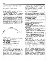
You will need to 

bend  the  ther­

mocouple  at  a 

90· 

angle  so  that  you 
can  fasten  the 
t h e r m o  c o u p l e  
block

· 

to  the  out­

side  kiln  case.  To 

bend,  first  break 

off  one  of  the 
ceramic insulators 

squeezing with pliers. 

Then bend the thermocouple where it Will extend into 

the firing chamber by 

-

11/2" 

when the thermocouple 

block  is  pressed  against  the  outside 

kiln 

case.  Hold 

thermocouple with pliers when bending. 

5. 

Position  outer  part  of  thermocouple  sideways  or 

downwards  against  the  kiln  case.  (Avoid  placing  the 

thermocouple  block  above  the  peephole,  which  would 
expose  it  to  heat  rising  from  the  peephole.)  Place  the 
thermocouple  holddown  bracket  over  thermocouple 

INSTALLING THE PORTABLE P 2000 

block  and  drill  two 

1/8 

holes.  Fasten  with  screws 

provided. 

Do not fire kiln without holddown bracket in place, 

because your kiln will overfire if the thermocouple 
should fall out. 

6. 

Plug your  kiln  or furnace into the P 

2000. 

7. 

If your 

kiln 

has switches, turn aU switches to the On 

or  High  position.  Leave  all  your  kiln's  switches  on  full 

when firing your kiln with the P 

2000. 

If  you're  using a  kiln  sitter  or  limit  timer 

as 

a  back 

up shut-off for the 

2000, 

place a cone in the kiln sitter. 

Set the limit timer for half an hour longer than expected 
firing  time.  It  will  be necessary to  use  a  new  cone  for 

every firing even if the previous cone didn't bend. 

9. 

If you decide not  to use the kiln sitter or limit timer 

as a  back  up  shut-off,  disconnect limit  timer.  Raise the 
kiln sitter weight, press in the plunger, and gently lower 
the  weight.  Your 

kiln 

sitter  is  now  on  manual  control. 

Do not use the firing gauge to lock the kiln sitter weight 
in the up position, for this could damage the kiln sitter. 

Содержание UDC2000

Страница 1: ...U DC 2000 INSTRUCTION MANUAL This is the roadmap that will unlock the magic in your UDC 2000 Study and save for future reference ...

Страница 2: ...anted for two years This warranty includes immediate technical assistance via a toll free telephone number and complete replace ment of the controller if necessary For technical assis tance dial 1 800 423 9883 Your model and serial number is OC2003 0 0080 0000 00 0111 Here s how to remove the controller from your kiln in the event that you need to return it to the factory under warranty 1 Loosen t...

Страница 3: ... into the drilled peephole plug provided Place I eephole plug into the top peephole of your lr iln 3 You will need to bend the ther mocouple at a 90 angle so that you can fasten the t h e r m o c o u p l e block to the out side kiln case To bend first break off one of the ceramic insulators b y squeezing with pliers 4 Then bend the thermocouple where itWill extend into the firing chamber by 1 11 2...

Страница 4: ...ram into the controller We will show you how Function Message All the adjustments made on the controller are organized under 8 Set Up Modes You must have the oorrect Set Up Mode displayed on the screen before making an adjustment Then you must press the FUNC key until the adjustment you are making appears in the display window This adjustment display is called a Function Message 3 Normal Temperatu...

Страница 5: ...ayed If you do not touch a key after a minute the display goes back to normal temperature display Press the SET UP key again to get one of the eight Set Up Modes in the bottom of the display Then press the top left FUNC function key Each time you press the FUNC key you will see a different message These mes sages are the Function Mes sages for the Set Up Mode you are in For instance CYC TI is a Fu...

Страница 6: ...se this later At this point the Set Up Modes and their Function Messages will probably read like Greek to you Don t let this concern you You will probably never use most of them they re already set up at the factory for you But we will explain fully how to make the Set Up adjust ments you will need 5 DISPLAY MESSAGES Display Messages While Firing a Program When you re firing a program the controll...

Страница 7: ...G and six soaks The SPPROG program is the heart of the controller The third method is with the SPRAMP program SPRAMP is a single ramp program The controller is either in a program SPPROG or SPRAMP or it is in Single Set Point When the control ler is out of the SPPROG and SPRAMP programs it is automatically in Single Set Point Single Set Point Firing The controller goes into Single Set Point right ...

Страница 8: ...when segment one runs out of time If you don t care whether or not the furnace has reached the soak temperature when the soak timing begins enter 0 under SOKDEV If you want the controller to begin timing the soak only after the furnace has reached the soak tempera ture enter a number If you enter 5 that means the controller will stop the soak timing whenever the fur nace temperature dips lower tha...

Страница 9: ...hedule 4 The display now reads ENAb SPROG Press the FUNC key STRSEG will ap pear in the bottom of the dis play Use the arrow keys to enter the first segment your firing is starting with This will usually be 1 5 Press FUNC again ENDSEG will appear in the bottom of the display Enter the last segment of your schedule using the arrow keys FIRING 1 I Toccr j I tJ IF I 1 5 p l1F E rJ II E G If you are f...

Страница 10: ...ogram you can enter ramp time in minutes or in degrees of rise per hour In the SPRAMP program that you are in now you can enter only minutes 9 3 Press FUNC again to get FINLSP final set point Use the arrow keys to enter the temperature you are firing to The furnace is set for 10000 F in this example 4 Press DISP to get back to the normal temperature display 1 nnnF IUUU F l p LIII L l Press RUNIHOL...

Страница 11: ... Message Change the settings with the arrow keys If the arrow keys have no effect on a setting bring up the TUNING Set Up Mode and then the LOCK Func tion Message Change the LOCK to none make the adjustments you need in the other Set Up Modes and then restore the LOCK REFERENCE Trouble Shooter KEYERR WHEN YOU PRESS RUN HOLD Both firing schedule s the 12 segment SPPROG and the single ramp SPRAMP ar...

Страница 12: ..._ ___ r I I L I L I I _ H 1 L r L L I L I I 1 1_ _ r 1 __ _ _ _ J 1 L _ _ H I J L f 1_ L _ _t I_I f r 1_ I 1 _ _ t f _ _ L _ t I 1 _ 1 L L L _ _ L 1 I II I T _ 1 L jl_t 1 i 1 L 1 1 L _ 1 1 r T I l I L I I lLT t T L ot r u trrf LI_ T HOURS Function Seg Enter This Display Function Seg Enter This Display ment Value Prompt ment Value Prompt Start SG4 SP Soak Set 4 SG9 RP Point End SG4 TI Soak Time 4 S...

Отзывы: