background image

away from direct sunlight, rain or snow. The best suggested location for the 
remote sensor for outdoors is under the eave on the north side of the building. 

NOTE:


When the temperature falls below freezing, the batteries in the 

outdoor remote sensor may have reduced voltage supply and a shorter 
effective range. We recommend using lithium batteries at temperatures of 
32°F (0°C) and below. 
 

BATTERY INSTALLATION 

REMOTE SENSOR 

NOTE: Install the batteries; select the temperature in °C or °F before 
mounting the remote sensor. 


Remove the screws from the battery compartment with a small Phillips 
screwdriver. 


Install 2 “AA” size alkaline batteries (not included) matching the 
polarities shown in the battery compartment. 


Replace the battery compartment door and secure the screws. 


Secure the remote sensor in the desired location. 

MAIN UNIT 


Remove the battery compartment door. 


Install 2 batteries (UM-3 or “AA” size 1.5V) matching the polarity as 
shown in the battery compartment. 


Replace the battery compartment door. 


LOW BATTERY WARNING 

A low-battery indicator [ 

] will appear next to the indoor or remote data 

reading line of the main unit warning that the corresponding batteries need 
replacement. 

10 

GETTING STARTED 

WEATHER DISPLAY 

After batteries are installed; remote sensor will transmit temperature data at 45 
second intervals. The main unit may take up to two minutes to receive the initial 
readings. Upon successful reception, remote temperature will appear on the 
top line of the main unit’s display .The main unit will automatically update 
readings at 45-second intervals. 

After communication between the main unit and remote sensor has been 
established, secure the remote sensor in the desired location. 

If no signal is received from the remote sensor within two minutes, dashes [

- - -

will be displayed. Press and hold the 

DOWN (

T

)

 button on the main unit for 

two seconds to initiate another signal search. 
 

PLACEMENT OF THE UNITS 

The main unit can be placed on any flat surface 

indoors

The remote sensor 

can be placed 

indoors

 or 

outdoors

, on a flat surface or mounted on the wall.


REMOTE AND INDOOR TEMPERATURE   

The remote temperature information line is located on the top line of the main 
unit’s display with abbreviation 

OUT 

next to it. 

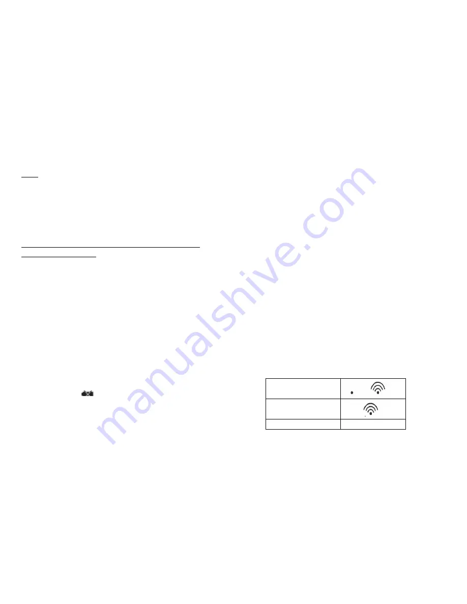
The wave icon is located above the 

OUT

 indicates the reception status from the 

remote sensor.   
There are three following types of the reception status may be displayed: 

The unit is in a searching 
mode. 


Temperature reading is 
securely registered. 


No signals detected. 

       - - - 

Содержание TS03

Страница 1: ...G 9 GETTING STARTED 10 PLACEMENT OF THE UNITS 10 REMOTE AND INDOOR TEMPERATURE 10 MAXIMUM AND MINIMUM READINGS 11 LOST COMMUNICATION 11 TRANSMISSION COLLISION 12 CALENDAR AND CLOCK DISPLAY MODES 12 MANUAL SETTINGS 12 CLOCK ALARMS 13 SNOOZE 14 PRECAUTIONS 15 TROUBLESHOOTING 15 SPECIFICATIONS 16 FCC STATEMENT 17 DECLARATION OF CONFORMITY 18 STANDARD WARRANTY INFORMATION 19 ...

Страница 2: ...tructions as well as technical specifications and precautions you should know 4 PRODUCT OVERVIEW MAIN UNIT FEATURES Precise Quartz Clock 12 or 24 hours Time Format Dual crescendo Time Alarm with Snooze Day of the week displayed in English Spanish French German and Italian Wireless Reception of the Temperature from the Remote Sensor to the Main Unit from up to 100 feet 30 meters away Minimum and ma...

Страница 3: ...ses the parameters Activates manual remote channel search Disables time alarms W and S and Ice Warning Alarm F ALARM ON OFF button Allows toggling between the calendar display and three time alarm modes Allows programming available alarms G MEM button Toggles between current minimum maximum readings of the indoor and remote temperature Clears the temperature memory H WALL MOUNT RECESSED OPENING Ke...

Страница 4: ... remote sensor before the main unit Insert batteries before first use matching the polarity in the battery compartment Press RESET after each battery change with a paper clip or similar tool During an initial setup place the main unit close to the remote sensor After reception is established the remote temperature will appear on the main unit s display position the remote sensor and the main unit ...

Страница 5: ...corresponding batteries need replacement 10 GETTING STARTED WEATHER DISPLAY After batteries are installed remote sensor will transmit temperature data at 45 second intervals The main unit may take up to two minutes to receive the initial readings Upon successful reception remote temperature will appear on the top line of the main unit s display The main unit will automatically update readings at 4...

Страница 6: ...eption please perform the following steps Bring the main unit and remote sensor close together 12 Remove four 4 small screws from the back of the remote sensor with small Phillips screwdriver and open the battery compartment Remove the batteries from the battery compartment and reinstall them in the same manner Remote sensor LED indicator will flash showing transmission of the signal Remove the ba...

Страница 7: ...ttons Press ALARM ON OFF button again The minute digits will flash Adjust the minutes using UP or DOWN buttons Press ALARM ON OFF button again to confirm and the weekday alarm 14 time will be set Set Single S day alarm if desired in the same manner SETTING THE ICE WARNING ALARM PRE AL If Weekday W or Single day S alarm is set the Ice Warning Alarm Pre AL can be programmed Press ALARM ON OFF button...

Страница 8: ...remote sensor Remote sensor Data does not match data on the main unit Initiate manual sensor search Press and hold DOWN button on the main unit 16 SPECIFICATIONS Main Unit Indoor Temperature Proposed operating range 23 0 F to 122 0 F 5 C to 50 C Temperature resolution 0 2 F 0 1 C User selectable F or C temperature display Maximum number of remote sensors 1 one included RF range Maximum 100 feet 30...

Страница 9: ...ion which can be determined by turning the equipment off and on the user is encouraged to improve or correct turning the interference by one or more of the following measures Reorient or relocate the receiving antenna Increase the separation between the equipment and receiver Connect the equipment to an outlet on a circuit different from that to which the receiver is connected Consult the dealer o...

Страница 10: ...our Customer Service at 1 866 443 3543 Please direct all returns to the place of the original purchase Should this not be possible contact Hideki Customer Service for assistance and to obtain a Return Merchandise Authorization RMA Returns without a return authorization will be refused Please retain your original receipt as you may be asked to provide a copy for proof of purchase Hideki Electronics...

Отзывы: