background image

32

https://extranet.honeywell.com

7

Route the interface and power cables from the wall to the reader 
through one of the three holes in the base of the swivel.

8

Route the cables through the swivel ball, being careful to ensure that 
the cables are on the same side of the connectors on the reader. Do not 
cross the cable inside the ball. Leave about 5-6 cm of excess cable.

9

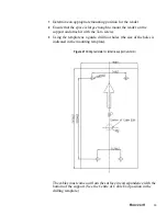
Attach the swivel to the wall using the three screw holes, paying 
attention to the right position as shown in 

Figure 15

. (Check the arrow 

UP inside the base.)

10

Fix the swivel ball on the support by giving the desired slope. The 
swivel ball has a key to prevent you from installing the ball upside 
down.

11

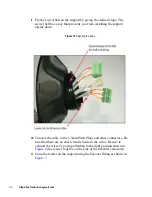
Connect the cable to the 3.5mm Pitch Plugs and other connectors. Be 
sure to connect the wires by paying attention to the right position 
shown in 

Figure 6

 (the screws must be on the side of the Ethernet 

connector). Be sure that there are no short circuits between the wires.

12

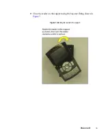
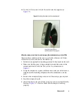
Use the bayonet fitting shown in 

Figure 7

 to close the reader.

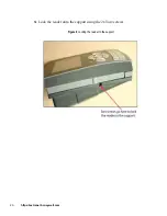
13

Use the 2x Torx screws to lock the reader onto the support. 

Mounting the device on the turnstile mount

This support is used for installing the reader on horizontal surfaces. 
Typical installation is for the use on the turnstile.

Figure 20 

Turnstile support (front and back views)

Содержание Tema-Voyager Compact

Страница 1: ...May 2014 2014 Honeywell All rights reserved 800 07074 Rel 2 0b Tema Voyager Compact Installation Guide ...

Страница 2: ...merchantability and fitness for a purpose and makes no express warranties except as may be stated in its written agreement with and for its customer In no event is Honeywell liable to anyone for any direct special or consequential damages The information and specifications in this document are subject to change without notice Copyright 2014 Honeywell International Inc Trademarks Tema VoyagerTM is ...

Страница 3: ...iii Support and other contacts For technical assistance call your nearest Honeywell office ...

Страница 4: ...iv https extranet honeywell com ...

Страница 5: ... warranty 5 Confidentiality 6 Device overview 7 Preparing for installation 8 Contents of the kit 8 Readers 8 Supports 8 Toolkit for reader 8 Toolkits for supports 9 Mounting tools 10 Wire characteristics 10 Power supply wire 10 Ethernet connector and cable 11 Input output RS485 wire 11 Mounting the device 13 Device connectors 13 Mounting the reader on the support 14 Mounting the reader on the wall...

Страница 6: ...ts 36 Outputs 37 External relays powered by the reader 37 Connecting the door lock directly using an external power supply 38 Jumpers 39 Voyager door backup line 40 Voyager door module 42 Technical specifications 44 Regulation 47 FCC Notice 47 Industry Canadian Compliance Statement 48 Australian CTick Conformity 48 Appendix 1 Internal Jumpers 49 Recycling 51 ...

Страница 7: ...all the fire and life safety codes pertinent to the installation These fire and safety codes vary from city to city and you must get approval from local fire officials whenever using an electronic product to control a door or other barrier Use of egress buttons for example may be illegal in some cities In most applications single action exit without prior knowledge of what to do is a life safety r...

Страница 8: ...rference at his own expense Disclaimer Product Liability Mutual Indemnification If a Customer receives a claim that a Product or any component thereof has caused personal injury or damage to the property of others Customer shall immediately notify Honeywell S r l Italy in writing of all such claims Honeywell S r l Italy shall defend or settle such claims and shall indemnify and hold Customer harml...

Страница 9: ...r and remove the unit s and all packing material Retain the container and all the packing materials They may be used again for reshipment of the equipment if needed 2 Inspect the contents to see if anything is missing If you notice any missing items send an e mail to temaline orders honeywell com 3 Visually check the contents If you see any damage do the following a If shipping has caused damage t...

Страница 10: ...he equipment Your original purchase order number invoice number and if the unit is still under warranty A new purchase order number if the unit is not under warranty From the customer service department obtain the Return Merchandise Authorization RMA Show the RMA number on all packages shipped Packages which are not marked with an RMA number will be refused at the factory and returned to you COD C...

Страница 11: ...defective as a result of misuse improper storage incorrect installation operation or maintenance alteration modification accident or unusual deterioration of the Product due to physical environments in excess of the limits set forth in Product manuals THERE ARE NO WARRANTIES WHICH EXTEND BEYOND THIS PROVISION THIS WARRANTY IS IN LIEU OF ALL OTHER WARRANTIES WHETHER EXPRESS IMPLIED OR STATUTORY INC...

Страница 12: ...on as confidential Customer shall acquire no rights in the design of the Products or the related materials except to use such information solely for the purpose of and only during the time it sells the Products Customer shall not copy the design of any of the Products or use or cause to be used any Product design or related materials for its own benefit or for the benefit of any other party The co...

Страница 13: ...rols and time and attendance systems These installation instructions contain the following information Mounting instructions Connecting the reader to the network and door Temaline recommends that before you begin read and familiarize yourself with these instructions This preparation should facilitate the installation ...

Страница 14: ...clude a toolkit for the reader that contains the following items Label Name Description VCU 01xxxxxxxxxx Voyager Compact Unit HID Prox VCU 02xxxxxxxxxx Voyager Compact Unit MIFARE VCU 03xxxxxxxxxx Voyager Compact Unit HID Prox MIFARE VCU 04xxxxxxxxxx Voyager Compact Unit iClass VCU 05xxxxxxxxxx Voyager Compact Unit iClass HID Prox VCU 06xxxxxxxxxx Voyager Compact Unit Sokymat Prox VCU 07xxxxxxxxxx...

Страница 15: ...stile support toolkit contains the following items 1 Balance resistors kit and diodes 1 RS 485 connector with cable 1 Jumper Quantity Description Quantity Description 1 Tamper switch with cable 1 Drilling template 4 Screws for Fisher plug S5V 4 Plastic plug Fisher S5C 2 Torx screws for reader closing Quantity Description 1 Tamper switch with cable 1 Drilling template 4 Screws for turnstile 2 Torx ...

Страница 16: ... with a smaller AWG Power supply wire The Voyager device can be powered either with a 10V 30V DC power supply or 48V PoE To determine the correct size of the power cable see the table below Warning Max voltage cable drop allowed must not exceed 0 8 VDC when the voltage is 12V Typical input current is 500mA The tables below show the values for one reader If more than one reader is connected to the ...

Страница 17: ...85 wire Input wires Use a twisted pair cable for the contacts connections AWG24 or AWG26 is recommended for the best wire recovery behind the reader The following table lists wire gauges and distances for inputs contacts Max distance m from the Power Supply for 12V Max distance m from the Power Supply for 24V AWG mm2 Ohm km 30 190 20 0 52 34 20 125 22 0 35 52 12 75 24 0 2 85 8 45 26 0 13 137 AWG m...

Страница 18: ...p is considered typical RS 485 wire Cable spec UL 24 AWG 85ohm Km twisted Because the RS 485 is used for door backup line between the two readers installed on the two sides of the door Also the RS 485 is used for connection of a Voyager device with a Voyager door module installed on the safe side of the door where the cable is usually short AWG mm2 Ohm km Max distance m 20 0 52 34 550 22 0 35 52 3...

Страница 19: ...r a good performance install the reader at least 5 cm away from the metal surface Device connectors All the connections are on the back of the reader inside the round area Figure 1 Connectors layout Connector Function Specification J1 POE Ethernet interface RJ45 Female Connector P4 Output interface 5Pin 3 5MM pitch Header connector P5 TAMPER Switch interface 2Pin 2 5MM Pitch Header connector P6 RS...

Страница 20: ...not need to open the reader to install it on the support Warning If you do not use the tamper close the P5 connector with the jumper included in the toolkit Mounting the reader on the wall mount Use this support to install the reader on a wall P7 Inputs and DC power interface 6Pin 3 5MM Pitch Header connector SW1 RS 485 length settings 2Pin 1 27MM DIP switches Connector Function Specification Figu...

Страница 21: ...external pipe To install the reader on a wall mount 1 Determine an appropriate mounting position for the reader 2 Make sure that the space is large enough to mount the reader on the support and close the Torx screws See the dimensions in Figure 3 Figure 3 Wall mount positioning ...

Страница 22: ...ng the template as a guide drill four holes the size of the holes is indicated on the template The cables coming from the pipe embedded in the wall shall be on the bottom of the support not center or top See the Centre of Cable Exit position in the drilling template Figure 4 Wall mount drilling template unit mm ...

Страница 23: ...ropriate guide as shown in Figure 5 5 Route the interface and power cable from the wall pipe to the reader Leave about 5 6 cm of excess cable 6 Attach the support to the wall using the 4 screws provided with the support Figure 5 Installing the tamper switch ...

Страница 24: ...the wires There is only one way to insert the connectors see Figure 6 8 Plug the RJ45 connector into the Ethernet port and other cables if present 9 Arrange the cables so that the connectors are on the same side of their sockets without crossing the cables 10 Check the right position of the gasket Figure 6 Cable illustration for tamper switch installation ...

Страница 25: ...19 11 Close the reader on the support using the bayonet fitting shown in Figure 7 Figure 7 Attaching the reader to the support ...

Страница 26: ...20 https extranet honeywell com 12 Lock the reader onto the support using the 2x Torx screws Figure 8 Locking the reader to the support ...

Страница 27: ... install the reader on a swivel base This support gives the reader the desired slope top down within a 24 degree range 12 to 12 The swivel support can be installed either on a flat surface horizontal or vertical or directly on a junction box Figure 9 Swivel support types ...

Страница 28: ...22 https extranet honeywell com To mount the reader on a swivel support 1 Determine an appropriate mounting position for the reader on the wall Figure 10 Exploded view of swivel support ...

Страница 29: ...23 2 Make sure that the space is large enough to mount the reader on the support and screw in the Torx screws See Figure 11 Figure 11 Space required to install swivel support ...

Страница 30: ...3 Center the drilling template on the center of cables exit and using the template as a guide drill three holes the size of the holes is indicated on the mounting template in Figure 12 Figure 12 Swivel mount drilling template unit mm ...

Страница 31: ...4 When the installation is on a junction box fixed into the wall center the template on the existing screws of the junction box and drill the third hole the lowest one Figure 13 Swivel mount using gang box ...

Страница 32: ...xtranet honeywell com The cables must come out from the wall in correspondence with the bottom of the support See the position on the drilling template 5 Insert the tamper if used Figure 14 Installing the tamper ...

Страница 33: ...27 6 Attach the IP65 cover to the swivel body using two screws inserted from the back see Figure 15 then check to make sure that the tamper works properly Figure 15 Installing the tamper ...

Страница 34: ...w in the base of the swivel Attach the swivel to the wall using the three holes paying attention to the correct position Check the arrow UP inside the base Warning For IP65 installations make sure that the waterproof plug on the back of the support is inserted into the hole in the wall Figure 16 Attaching the swivel to the wall ...

Страница 35: ...ugh the swivel ball ensuring that the cables are on the same side as the connectors located on the reader Avoid crossing the cables inside the ball Leave about 5 6 cm of excess cable Figure 17 Routing the cables into the swivel ...

Страница 36: ...10 Connect the cable to the 3 5mm Pitch Plugs and other connectors Be sure that there are no short circuits between the wires Be sure to connect the wires by paying attention to the right position shown in Figure 6 the screws must be on the side of the Ethernet connector 11 Close the reader on the support using the bayonet fitting as shown in Figure 7 Figure 18 Adjusting the slope ...

Страница 37: ...he space is large enough to mount the reader on the support and attach it with the Torx screws See dimensions in Figure 11 3 Using the template as a guide drill three holes the size of the holes is indicated on the mounting template when the installation is on the wall 4 Remove the waterproof plug on the swivel base using a pair of pliers 5 Insert the tamper if used 6 Attach the base to the swivel...

Страница 38: ... ball on the support by giving the desired slope The swivel ball has a key to prevent you from installing the ball upside down 11 Connect the cable to the 3 5mm Pitch Plugs and other connectors Be sure to connect the wires by paying attention to the right position shown in Figure 6 the screws must be on the side of the Ethernet connector Be sure that there are no short circuits between the wires 1...

Страница 39: ...ch it with the Torx screws 3 Using the template as a guide drill four holes the size of the holes is indicated in the mounting template The cables must come out from the surface in correspondence with the bottom of the support See the Centre of Cable Exit position in the drilling template Figure 21 Drilling template for turnstile support unit mm ...

Страница 40: ...nectors Be sure that there are no short circuits between the wires Be sure to connect the wires by paying attention to the correct position shown in Figure 6 The screws must be on the side of the Ethernet connector 8 Use the bayonet fitting shown in Figure 7 to close the reader on the support 9 Lock the reader onto the support with the 2x Torx screws Turnstile mounting using the swivel support The...

Страница 41: ...tton request to exit However the inputs can also be used as general purpose inputs The typical connection for digital dry contacts is shown in Figure 22 Temaline recommends that you establish an electrical environment where the cables are well separated even at short runs especially to the power cables or external cables which can be essentially subjected to interference or lightning Use a twisted...

Страница 42: ...sistance 1210 Ohm Temaline recommends that you establish an electrical environment where the cables are well separated even at short runs especially to the power cables or external cables which can be essentially subjected to interference or lightning Use a twisted pair cable for the contact cables Make sure that the cables correspond in size to the norms indicated in section INPUT WIRES Max conta...

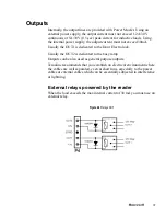
Страница 43: ...ted to the Door Electro lock Usually the OUT2 is dedicated to the busy lamp Outputs can be also used as general purpose outputs Temaline recommends that you establish an electrical environment where the cables are well separated even at short runs especially to the power cables or external cables which can be essentially subjected to interference or lightning External relays powered by the reader ...

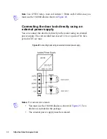
Страница 44: ... supply You can connect the door lock directly to the reader using an external power supply The current shall not exceed 1 2A or a peak of 5A for a period of 0 5 sec max Notes For not resistive loads You must use the 1N4004 diodes as shown in Figure 25 Two diodes are included in the package The external power supply must be isolated Figure 25 Connecting loads using an external isolated power suppl...

Страница 45: ...on for the RS 485 network a RS 485 allows the wiring of a multidrop communication network of up to 1200 m in length SW1 DIP switches Pin1 Pin2 set in ON position b RS 485 Port communication network should not exceed 15 m in length SW1 DIP switches PIN1 PIN2 set in OFF position Figure 26 Jumpers Jumper ON OFF Function SW1 1 2 ON Long distance up to 1200m OFF Short distance up to 15m ...

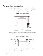
Страница 46: ...an have a backup connection between the devices using the RS 485 serial line with encrypted protocol as shown in Figure 27 The typical connection for the Voyager door backup line appears as shown in Figure 28 You can set the RS485 wiring length using the SW1 jumpers For more information on jumpers see Jumpers on page 39 Figure 27 Use of Voyager door backup line Figure 28 Voyager backup line connec...

Страница 47: ...41 The use of the Voyager door backup line must be enabled and configured from the EBI supervision center For more information refer to the Temaline Access Control Guide ...

Страница 48: ... and the Voyager door module is installed on the secure one The input output for the management of the door Strike Request to exit and Door sense are connected to the door module The communication between the Voyager device and the door module occurs through the RS485 serial line with encrypted protocol The typical connection of the Voyager door module line appears as shown in Figure 29 For more i...

Страница 49: ...t the RS485 wiring length using the SW1 jumpers For more information on jumpers see Jumpers on page 39 The use of Voyager door module must be enabled and configured from the EBI supervision center For more information refer to the Temaline Access Control Guide Figure 30 Voyager Door Module connection ...

Страница 50: ...5 6W 500 mA 12VDC VCU 06 5W 400 mA 12VDC VCU 07 6W 500 mA 12VDC Weight 0 46 kg Dimensions 40 x 103 x 163 mm Protection level IP65 Operational temperature VCU 01 20 55 C VCU 02 20 60 C VCU 03 20 55 C VCU 04 20 60 C VCU 05 20 55 C VCU 06 20 60 C VCU 07 20 60 C Storage temperature 20 70 C Storage relative humidity 0 95 without condensation Display 3 5 230 400 DPI RGB 320x240 True Color TFT LCD Audio ...

Страница 51: ...tal inputs Mode select Supervised inputs for four statuses Normal Alarm Cut and Short Digital inputs with two statuses Open Close Current 0 10mA for each input Voltage 6 VDC maximum 0V minimum Outputs Number 2 Type Power Open Drain Mosfet Load Inductive load admitted When supplied directly from the reader Current 30mA Voltage 12 VDC When supplied from external power supply Current 1 2A contiguous ...

Страница 52: ...2002 EN 50133 1 2010 EN 50133 2 2010 EN 50133 7 2010 CTick For more information on CTick regulation see Australian CTick Conformity on page 48 Industry Canadian For more information on Industry Canadian compliance see Australian CTick Conformity on page 48 FCC Part15 Class B For more information on FCC Part15 Class B rules see FCC Notice on page 47 UL 294 S319 pending Environmental impact RoHS WEE...

Страница 53: ...d and used in accordance with the instructions may cause harmful interference to radio communications However there is no guarantee that interference will not occur in a particular installation If this equipment does cause harmful interference to radio or television reception which can be determined by turning the equipment on and off the user is encouraged to try to correct the interference by on...

Страница 54: ...ur le material broilleur du Canada Australian CTick Conformity Brand Honeywell Model numbers VCU 017015EN1N00 VCU 017015EN1N01 VCU 027015EN1N00 VCU 027015EN1N01 VCU 037015EN1N00 VCU 037015EN1N01 VCU 047015EN1N00 VCU 047015EN1N01 VCU 057015EN1N00 VCU 057015EN1N01 Attestation Number HSQ CTick 110014 For compliance levels 1 2 and 3 in Australia As required by notices under Section 182 of the Australi...

Страница 55: ...d is restored to factory configuration when the jumper is closed All the data present in the memory and in the database of the device is lost and the communication parameters reset to the factory default values The IP address of the device is set to 160 221 230 127 After the restart the jumper must be set back to Open This will enable you to work again with the device 4 Linux Console activation Op...

Страница 56: ...50 https extranet honeywell com Note Internal jumpers can be used only for maintenance purpose and only on request of Technical Assistance Center personnel ...

Страница 57: ...e August 13 2005 Honeywell commits when requested by the customer to the collection treatment recovery and disposal of the apparatus produced Customers in the European Union are advised to dispose of this product at the end of its useful life in accordance with the applicable local laws regulations and procedures ...

Страница 58: ...52 https extranet honeywell com ...

Отзывы: