22 Fault Tracing
Honeywell
5
5. FAULT TRACING
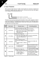
When a fault is detected by the inverter control electronics, the drive is stopped and
the symbol F together with the ordinal number of the fault and the fault code appear
on the display in the following format, e.g:
The fault can be reset by pressing the Stop button on the control keypad or via the I/
O terminal or fieldbus. The faults with time labels are stored in the Fault history menu
which can be browsed. The different fault codes, their causes and correcting actions
are presented in the table below.:
Fault
code
Fault name
Possible cause
Correcting actions
1
Overcurrent
Inverter has detected too high a
current (>4*I
N
) in the motor cable:
• Sudden heavy load increase
• Short circuit in motor cables
• Unsuitable motor
Check loading.
Check motor size.
Check cables.
2
Overvoltage
The DC-link voltage has
exceeded the internal safety limit:
• Too short a deceleration time
• High overvoltage spikes in
mains
Increase the deceleration
time (P.4.3).
3
Earth fault
Current measurement has
detected extra leakage current at
start:
• Insulation failure in cables or
motor
Check motor cables and
motor.
8
System fault
• Component failure
• Faulty operation
Reset the fault and restart.
Should the fault recur, con-
tact technical support.
9
Undervoltage
The DC-link voltage has
exceeded the internal safety limit:
• Most probable cause: too low
a supply voltage
• Inverter internal fault
• Power outages
In case of temporary supply
voltage break reset the fault
and restart the inverter.
Check the supply voltage. If
it is adequate, an internal
failure has occurred.
Contact technical support.
Table 5.1 : Fault codes
F1 02
Fault code (02 = overvoltage)
Fault ordinal number (F1 = latest fault)


