

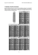


System 57 Quick Start Guide
05701-M-5026 MAN0839 Issue 1
x 3
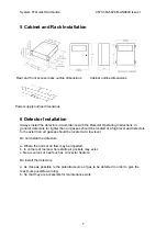
EOL
5.1k
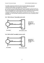
+
-
-
+
IN-
23
21
IN+
330
Fuse
Safety Barrier
e.g. MTL 728
Detectors
Safe Area
Hazardous Area
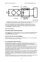
5704 Hex Card
Notes: 1. Earth Leakage must not be used with single or dual barriers since the 0V is
connected to IS ground. If earth leakage is required an isolating barrier must be used.
The diagram shows the detector connections for Channel 1. Channel 2, 3 and 4 connections
are similar and their terminal connection numbers are shown in section 7.
2. A suitable barrier specification is a 28V 300 ohm Shunt Barrier with 50mA minimum
current capability for short circuit survival.
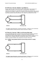
Fire Card Link Settings:
LK150- Earth Leakage Fault Detection Enable
.
Default position 1 to 2 to disable detection. Link 2 to 3 to enable the earth leakage detection
circuit.
IMPORTANT:
This link should be set on one fire card only and usually the card
connected to the Fire Status Panel.
LK101, 201, 301, 401- I.S. Input Compatibility.
Individual setting for inputs 1 to 4 respectively. Default position 1 to 2 for normal operation.
Link 2 to 3 when using an external I.S. barrier.
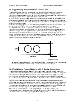
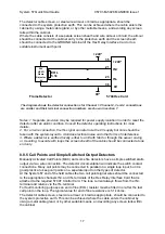
8.8.4 Separately Powered Detectors
Separately powered detectors (e.g. most IR, UV/IR Flame detectors) require three or four
wire connections. The detector documentation will indicate the 0V and +24V power
connections and the positive and negative loop connections. When using flame detectors it
is common practice to use only one detector per loop input.
At the System 57 end of the field cables the two detector signal wires should be connected
to the appropriate channels IN+ and IN- terminals of the Hex Relay Interface Card that is
attached to the required 5704F Control Card. The loop current always flows from the IN+
terminal and returns via the IN- terminal.
The power for the detector may be sourced from the System 57 power supply or a separate
field supply, whichever is most appropriate. In small systems, power can be obtained from
terminals 35 and 36 of the Hex Relay Interface Card, but care must be taken not to exceed
the maximum backplane current loading of 8A. A separate dc power distribution block is
recommended.
For fault monitoring purposes, an end of line (EOL) resistor must be fitted in or after the last
detector on the loop. The typical value for end of line resistance is 5.1k ohms.
16


