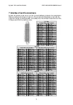
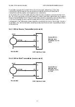
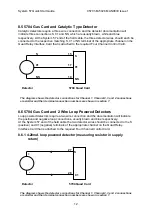
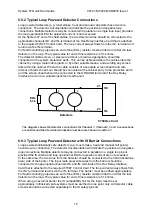
background image

System 57 Quick Start Guide 


05701-M-5026 MAN0839 Issue 1 


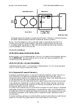
8.3.1 4-20mA loop powered detector (measuring resistor in supply 

return) 


01


28 

27 

Detector 

5701 Interface Card 

Sensor Drive Module 
Link Positions 13, 10 
& 4. 

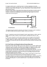
8.3.2 4-20mA loop powered detector (measuring resistor in supply 

positive line) 


NS


01


29 

28 

Detector 

5701 Interface Card 

Sensor Drive 
Module Link 
Positions 9, 6 & 1. 

8.4 5701 Gas Card and 3 Wire 4-20mA Transmitter 


CAUTION 


The power provided by the Single Channel Control Card is derived from the dc 

input to the System 57 (18V to 32V). Check that the transmitter to be connected is 

compatible with the actual supply voltage used. 

The maximum current that may be sourced from the field terminals of an individual 

Single Channel Control Card to power a field device is 500mA, however, the total 

current sourced from all the channels should not exceed the maximum backplane 

load current of 8A. 

10 

Содержание Sieger System 57

Страница 1: ...System 57 Quick Start Guide 05701 M 5026 MAN0839 Issue 1 0 ...

Страница 2: ...measuring resistor in supply return 10 8 3 2 4 20mA loop powered detector measuring resistor in supply positive line 10 8 4 5701 Gas Card and 3 Wire 4 20mA Transmitter 10 8 4 1 3 Wire Source Transmitter sink card 11 8 4 2 3 Wire Sink Transmitter source card 11 8 5 5704 Gas Card and Catalytic Type Detector 12 8 6 5704 Gas Card and 2 Wire Loop Powered Detectors 12 8 6 1 4 20mA loop powered detector ...

Страница 3: ...us areas 2 Designed for indoor use only 3 Not to be exposed to rain or moisture CAUTIONS 1 Use only approved parts and accessories with the System 57 control system 2 To maintain safety standards regular maintenance calibration and operation of the System 57 control system by qualified personnel is essential IMPORTANT NOTICES 1 Honeywell Analytics can take no responsibility for installation and or...

Страница 4: ...ed master time delayed update and rate of rise alarm facilities 4 part LCD display peak reading facility and detector performance monitoring 3 2 Fire Control Cards The 5704F fire control cards provide display and alarm facilities for a wide variety of fire detection products and provide up to four fire zone inputs compatible with most flame smoke and heat detectors and manual call points The statu...

Страница 5: ...date module provides a common alarm indication with new alarm event update It also provides 2 Outputs 1 relay 1 Darlington with selectable operation pulsed or continuous and an alarm and common alarm reset input It complies with ISA M DIN 19 235 It can be used with the optional master alarm update panel 3 6 Interface Cards There are 9 versions of interface card available 5 for 5701 Gas 2 for 5704 ...

Страница 6: ...nnected directly to the engineering card and provides the connection point for power supplied to the whole rack The field wiring from the engineering card is also on this card It provides a common power supply wiring point reverse polarity and short circuit protection and multi supply input capability ...

Страница 7: ... 0301 5704F Relay Interface assy 05704 A 0133 5704F Hex Relay Interface card 05704 A 0123 or or Blanking Panel 05701 A 0165 4 Channel Fire 05704 A 0146 Fire Status Panel 05704 A 0148 or Analogue output sink 04200 A 0145 source 04200 A 0146 mA Analogue output 05701 A 0285 Catalytic Sensor Drive modules 4 Channel Catalytic 05704 A 0144 4 Channel mA 05704 A 0145 or Analogue output sink 04200 A 0145 s...

Страница 8: ...etectors for lighter than air gasses should be located at a high level and detectors for heavier than air gasses should be located at a low level Do not install the detectors a Where the normal air flow may be impeded b In corners of rooms where static air pockets may exist c Near sources of heat such as convector heaters Do install the detectors a As close as possible to the potential source of g...

Страница 9: ...l 4 S 21 Relay 11 COM 22 Relay 12 COM 23 Channel 3 01 24 Channel 4 01 23 Relay 12 NC 24 Relay 12 NO 25 Channel 3 NS 26 Channel 4 NS 25 Relay 13 NO 26 Relay 13 COM 27 Analogue 24V 28 Analogue 0V 27 Relay 14 NO 28 Relay 14 COM 29 Analogue CH1 30 Analogue CH2 29 Relay 15 NO 30 Relay 15 COM 31 Analogue CH3 32 Analogue CH4 31 Relay 16 NO 32 Relay 16 COM 33 Remote Reset 34 Remote Inhibit 33 Ground 34 Gr...

Страница 10: ... be connected at one end i e at the detector or at the Interface Relay Card 8 2 5701 Gas Card and Catalytic Type Detector Catalytic detectors require a three wire connection and the detector documentation will indicate three connections S 01 and NS which are usually brown white and blue respectively At the System 57 end of the field cable the three detector wires should each be connected to the re...

Страница 11: ...dule Link Positions 9 6 1 8 4 5701 Gas Card and 3 Wire 4 20mA Transmitter CAUTION The power provided by the Single Channel Control Card is derived from the dc input to the System 57 18V to 32V Check that the transmitter to be connected is compatible with the actual supply voltage used The maximum current that may be sourced from the field terminals of an individual Single Channel Control Card to p...

Страница 12: ...gle Channel Display Card The exact terminals used vary depending upon whether three or four wire topology is used and the requirement for loop current source or sink configuration The Schematics below detail the connections for 3 wire current sink or source transmitters For other schematics including isolated and barrier refer to operating manual 05701 M 5001 8 4 1 3 Wire Source Transmitter sink c...

Страница 13: ...l 1 Channel 2 3 and 4 connections are similar and their terminal connection numbers are shown in section 7 8 6 5704 Gas Card and 2 Wire Loop Powered Detectors Loop powered detectors require a two wire connection and the documentation will indicate the positive and negative loop connections usually brown and blue respectively At the System 57 end of the field cable the two detector wires should be ...

Страница 14: ...s on the Quad Relay Interface Card that is attached to the required Four Channel Control Card The exact terminals used vary depending upon whether three or four wire topology is used the requirement for a loop current source configuration and the channel to be connected to The transmitter power connection 2 and 0V should be connected to a suitable dc supply N be used to power the transmitter T oth...

Страница 15: ...e loop The typical value for the end of line resistance is 5 1k ohms although this may need to be reduced when many detectors are fitted onto the loop An equivalent circuit of one fire input together with an example detector connection is shown below 8 8 1 Line Resistance Detectors should be located such that the line resistance of the cable required does not prevent correct operation As a general...

Страница 16: ...to the GROUND terminal of the Hex Relay Interface Card or to a suitable instrument earth point EOL 5 1k IN 23 21 Detectors IN 5704 Hex Card The diagram shows the detector connections for Channel 1 Channel 2 3 and 4 connections are similar and their terminal connection numbers are shown in section 7 8 8 3 Typical Loop Powered Detector with IS Barrier Connections Loop powered intrinsically safe dete...

Страница 17: ...tion Link 2 to 3 when using an external I S barrier 8 8 4 Separately Powered Detectors Separately powered detectors e g most IR UV IR Flame detectors require three or four wire connections The detector documentation will indicate the 0V and 24V power connections and the positive and negative loop connections When using flame detectors it is common practice to use only one detector per loop input A...

Страница 18: ...ugh the sensor casing or mounting to avoid earth loops the screen sheath of the cable should be connected at o end only 8 Manually Activated Call Points MAC and some fire detectors have a simple switch output via two wire connection The detector documentation will indicate connections Many call points may be connected in parallel on a single loop input but it is good practice to keep call points o...

Страница 19: ...ud or through the sensor casing or mounting the screen sheath of the ca avoid earth loops 8 Some fire detectors especially flame are equipped with a voltage free contact for th output and often with a second voltage free contact for fault outpu are easily connected to the fire card using a two wire connection The detector documentation will indicate the voltage free contact connections Although a ...

Страница 20: ...e detector junction box v 2 Where the detector is earthed locally either to an earth stud or through the detector casing or mounting to avoid earth loops the screen sheath of the cable should be connected at one end only Normally Closed Fault Contact Normally Open Alarm Contact 620 EOL 5 1k IN 23 21 Alarm Current Resistor IN Volt Free Output Detector 5704 Hex Card The diagram shows the detector co...

Страница 21: ...L EN50058 Performance 100 V V EN50271 Software and Digital Technologies Meets Exe isolation requirements for 50V operation EXAM BBG Pruef und Zertifizier GmbH EC type examination certificate BVS 04 ATEX G 001 X Note If compliance with the EC type examination certificate BVS 04 ATEX G 001 X is required refer to chapter 10 Special Conditions for Safe Use Ensure that all conditions therein are met 20...

Страница 22: ...der output may be in error by 5 fsd during some test conditions of the industrial standard if the connecting cables are not shielded with an outer screened cable Radiated Susceptibility 10V m over 50kHz to 1GHz Note The Part 2 conformity refers to installations using the System 57 cabinet For System 57 racks not supplied in cabinets or supplied in GRP cabinets the conformity is to Part 1 LV Direct...

Страница 23: ... clipping feature should be activated only in exceptional cases Irrespective of the operating mode of the analogue output the fault level and inhibit level shall be configured to different values outside the measuring range The signaling of faults and inhibits at the analogue output shall be activated If no local inhibit relays are configured a master inhibit relay shall be configured If no local ...

Страница 24: ...l 41 41 541 5877 Fax 41 41 541 5878 Email General Information Sales info kesn ch Accounts Department accounts kesn ch USA Office 233 Rogue River Highway 425 Grants Pass Oregon 97527 5429 USA Tel 1 503 206 0941 Fax 1 541 610 1646 Email General Information Sales info keison com Accounts Department accounts keison com Latin America Office World Trade Centre Apartado 0832 00708 Ciudad de Panamá República ...

Отзывы: